Ⅰ. Introduction to line protection
The line protection device is mainly used for the protection, measurement and control of the interval units of various voltage levels. It has perfect functions of protection, measurement, control, backup power supply and communication monitoring. The protection and control of the system provides a complete solution, which can effectively guarantee the safe and stable operation of the high and low voltage power grid and the plant power system.
Line protection not only protects the power line itself, but also protects equipment connected to the line, such as transformers, generators, etc. By cutting off the faulty circuit quickly, it can prevent the fault from causing damage to the equipment. When a fault occurs on the line, the rapid response of the protection system can help operators quickly locate the fault and take appropriate measures. This helps reduce outage time and restore power quickly.
Line protection is a key technology in the power system, which is used to detect and protect the safe and stable operation of power lines when faults occur. The line protection system detects abnormal conditions by monitoring the current, voltage and other parameters on the power line and comparing them with the preset protection settings. Once an abnormality is found, the protection system will quickly take action to cut off the faulty section, thereby preventing the fault from expanding .
Line protection is typically implemented using devices such as relays, sensors, and controllers. It can adopt different protection strategies according to different types of faults and line characteristics, such as overcurrent protection, distance protection, differential protection, etc. The goal of these protection strategies is to detect faults quickly and accurately, and isolate the fault by disconnecting the fault circuit or other control actions, so that the power system can continue to operate stably.
Line protection devices are generally composed of logic elements, executive elements, and measurement elements.
1. Logic element: According to the size and nature of the output of the measurement part, the logic state of the output, the order of appearance or their combination, the protection device works according to a certain Boolean logic and sequential logic, and finally determines whether it should trip or send a signal. And pass the relevant commands to the executive components. Logic circuits include or, and, not, delay start, delay return, memory, etc.
2. Executing element: According to the signal transmitted by the logic element, the task of the protection device is finally completed. Such as: tripping when fault occurs; signaling when abnormal operation; no action when normal operation.
3. Measuring element: measure the relevant physical quantity (such as current, voltage, impedance, power direction, etc.) input from the protected object, and compare it with the given setting value, and give "yes" and "no" according to the comparison result ", "greater than", "not greater than" and a group of logic signals with "0" or "1" properties, so as to judge whether the protection should be activated.
Ⅱ. The role of line protection in power system
1. Stable operation: Faults may cause voltage and frequency fluctuations in the power system, and even cause system imbalance. The quick response of line protection can help maintain the stable operation of the power system and reduce system instability.
2. Fault analysis: The line protection system is usually equipped with a fault recorder, which can record the electrical parameters when a fault occurs. These data are helpful for subsequent fault analysis and problem diagnosis.
3. Network stability: Faults may have a chain reaction on the entire power system, affecting the stability of the entire power grid. With accurate line protection, fault propagation can be avoided and the normal operation of the power network can be maintained.
4. It can be used in the classified maintenance of low-voltage lines in order to reduce the scope of power outages caused by personal safety electric shock accidents and grounding failures caused by power cuts.
5. The line protector can be used as an alarm system when the rated voltage is exceeded in the electrical equipment line. Another function of the line protector is to send an over-current alarm when the load current in the line exceeds the limit of the rated device. It has an alarm function for important equipment such as sites, equipment, and fire pumps that are affected by power outages, and performs power outages or power supply conversions.
6. It is used for protection against direct contact with high-voltage electric shock accidents. When the insulation layer of the power circuit is damaged and the grounding device fails, the line protector can cut off the power supply instantaneously when the fault current reaches the limit value of the leakage device.
7. When the rated voltage is generated in the electrical equipment line, the line protector can be used as an alarm system. Another function of the line protector is to send an over-current alarm when the load current in the line exceeds the limit of the rated device. It has an alarm function for important equipment such as sites, equipment, and fire pumps that are affected by power outages, and performs power outages or power supply conversions.
Ⅲ. Development stage of line protection
With the development of science and technology, line protection devices have gradually experienced four development stages: traditional relay relay protection-semiconductor transistor relay protection-integrated circuit relay protection-microcomputer protection
The first three stages can be approximated as conventional relay protection. Microcomputer protection has now become the mainstream application of all protection devices. The most notable difference in each stage is the change of the physical logic device of the protection device.
Development of line protection:
1. Digital protective devices: In recent decades, the rise of digital technology has promoted the further development of protective devices. Digital protection devices use digital signal processing techniques to collect, process and analyze power system parameters. These devices can implement more complex protection algorithms, improving the accuracy and speed of fault detection. In addition, digital devices can also be integrated with the communication network of the power system to realize remote monitoring and control.
2. Mechanical protection devices: Early power systems used mechanical protection devices such as overcurrent relays and circuit breakers. These devices are mainly based on mechanical motion and thermal response to detect current overload and short circuit and trigger the operation of the circuit breaker. This device is simple and reliable, but has certain limitations in terms of accuracy and speed of response.
3. Electronic protection devices: With the advancement of electronic technology, electronic protection devices have gradually replaced mechanical and electrical devices. These devices use electronic components such as transistors, integrated circuits, etc. to perform fault detection and protection actions. Electronic protection devices have higher precision, flexibility and programmability, and can realize various protection strategies.
4. Electrical protection devices: With the development of power systems, electrical protection devices, such as electromagnetic relays, have emerged. These devices use the principle of electromagnetic induction to detect abnormalities in current and voltage, and trigger protective actions through electromagnetic force. This stage of development increases the accuracy and speed of response of the protective device.
5. Electrical protection devices: Smart protection devices: A recent development trend is the application of artificial intelligence (AI) and machine learning to line protection devices. The intelligent protection device can learn and optimize the protection strategy according to the actual operation of the power system, which improves the adaptability to complex faults and changing conditions.
Ⅳ. Principle and setting principle of line protection
1. No time limit current quick break protection
Timeless current quick-break protection, also known as current stage I protection, is a protection that responds to current rise without time-limited (instantaneous) action, referred to as current quick-break protection.
working principle:
The figure above shows the current quick-break protection of the power supply line on one side. When point K1 at the end of line AB is short-circuited, protection 1 is expected to act instantaneously; when point K2 at the beginning of line BC is short-circuited, protection 2 is expected to act. According to the requirement of selectivity, protection 1 should not act. But in fact, when K1 and K2 points are short-circuited, the short-circuit current value flowing through protection 1 is almost the same, and protection 1 cannot distinguish between K1 point short-circuit and K2 point short-circuit. In order to make the protection 1 not operate when the K2 point is short-circuited, the operating current of the protection 1 must be greater than the maximum short-circuit current flowing through the protection 1 when the K2 point is short-circuited.
In this way, when the K2 point is short-circuited, the protection 1 does not act, and the protection 2 acts to remove the fault, which ensures the selectivity of the protection 1 and 2. Therefore, the operating current of the current quick-break protection should be set according to the condition of avoiding the maximum short-circuit current at the end of this section of the line (beginning of the lower section of the line).
Curve 1 is the variation curve of the short-circuit current in the maximum operation mode, and curve 2 is the variation curve of the short-circuit current in the minimum operation mode. Line 3 is the minimum operating current of protection 1. The intersection point of line 3 and curve 1 is M. When there is a short circuit from the installation of protection 1 to point M, protection 1 can operate. After point M, the short-circuit protection 1 cannot operate, and the selectivity of the protection 1 is guaranteed, and there is no current quick-break protection when the M-B section line is short-circuited, which is called the dead zone of the current quick-break protection.
The selectivity of the current quick-break protection is guaranteed by the operating current, which cannot protect the entire length of the line. Point N is the intersection of straight line 3 and curve 2. When the system operates in the minimum mode, the range of protection 1 is A-N, which becomes smaller, indicating that the range of current quick-break protection is greatly affected by the system operation mode. Protection 3 is set by avoiding the short-circuit current on the low-voltage side of the transformer, and the current quick-break protection can also protect the entire length of the line from the C substation to the transformer group line and penetrate deep into the high-voltage side of the transformer.
Setting principles:
In order to ensure selectivity, the primary action current of the current quick-break protection is set according to the maximum short-circuit current flowing through the protection installation when avoiding the three-phase short circuit at the end of the protected line. The reliability factor is generally 1.2~1.3, that is, the primary operating current of the protection is 1.2~1.3 times of the maximum short-circuit current flowing through the protection device when the three-phase short circuit at the end of the protected line is in the maximum operation mode.
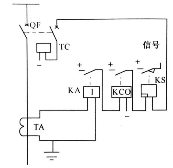
Wiring principle:
Single-phase current quick-break protection consists of current relay KA, export intermediate relay KCO and signal relay KS. Normally, the load current is less than the starting current of KA, KA does not act, and its moving contact is in the disconnected state. When there is a short circuit in the protected area, the short circuit current exceeds the operating current of KA, KA acts, the contact is closed to start KCO, and the KCO contact is closed to pass the positive power through the signal relay coil and the circuit breaker QF auxiliary contact to connect the circuit breaker tripping coil Y, The circuit breaker trips to remove the faulty line. At the same time, the signal relay KS acts to send out a signal.
The function of KCO: take advantage of its 0.06~0.08s delay action time to avoid the malfunction of quick-break protection caused by the discharge of the tubular arrester; increase the contact capacity.
2. Time limit overcurrent protection
Time limit overcurrent protection is referred to as overcurrent protection, and its operating current is set according to avoiding the maximum load current. The overcurrent protection has high sensitivity and a large protection range. It can not only protect the entire length of the line, but also protect the entire length of the next-level line or even further. It can be used as the near backup protection of the main protection of the line and the far backup protection of the lower line.
There are two types of overcurrent protection: one is that the action time after the protection is started is a fixed setting time, which is called definite time overcurrent protection; the other is that the action time is related to the magnitude of the overcurrent value, the greater the current, the faster the action , the smaller the current, the slower the action, which is called inverse time overcurrent protection.
The action time of the definite time overcurrent protection does not change with the magnitude of the short circuit current. The definite time limit is to set the protection of each section of the line according to the principle of time ladder. The farther away from the power supply direction, the shorter the time limit, and the closer the time limit is, the longer it is. Each time limit difference is greater than 0.5s. The time limit has nothing to do with the magnitude of the short-circuit current. The electromagnetic overcurrent protection device is set according to the definite time limit.
The action time of inverse time overcurrent protection decreases automatically with the increase of short circuit current. The characteristic of the inverse time limit is that the action time of the protection device changes with the magnitude of the short-circuit current. If the short-circuit current is large, the action time is short, and vice versa, the action time is long. The inductive overcurrent protection device works according to the principle of inverse time limit, but when the short-circuit current increases beyond a certain value, the action time is no longer shortened, and the current quick-break device operates at this time, showing the characteristic of definite time limit.
Setting principles:
The operating current of the overcurrent protection must be greater than the load current. The protection device does not operate at the maximum load current. When an external short circuit occurs in the next-level line, if the current relay of the current level has been activated, after the lower-level protection cuts off the fault current, the current level of protection should be can be returned reliably.
On a radial line with a single power supply, in order to meet the selectivity requirements, the action time limit of the overcurrent protection should be matched with that of the next-level adjacent line, that is, the action time limit of the upper level closer to the power supply should be shorter than that of the adjacent power supply. The action time limit of the next level of overcurrent protection is higher by △t. The action time of each level of overcurrent protection is set in this way, like a ladder, which is the so-called ladder-shaped time limit characteristic.
3. Single-phase ground protection of neutral point ungrounded system
Features:
The voltage and phase between the phases remain unchanged, the balance of the three-phase system has not been damaged, and it can continue to operate for a period of time, but long-term grounding operation is not allowed, especially the power system directly powered by the generator, because the voltage of the ungrounded relative to the ground increases To line voltage, if one phase is grounded for too long, it may cause a two-phase short circuit.
When a single-phase grounding occurs, a signal can be sent, so that the on-duty personnel can quickly take measures to eliminate the fault as soon as possible. The allowed continuous operation time of one-phase grounding system shall not exceed 2 hours at most.
The current passing through the grounding point is capacitive, and its size is three times that of the original relative ground capacitance current. It is not easy to extinguish, and may cause intermittent and periodic extinguishment and re-arcing of the arc at the grounding point.
The continuous intermittent arc of arc grounding is more dangerous, which may cause the resonance phenomenon of the line to generate overvoltage, damage the electrical equipment or develop into a short circuit between phases. Therefore, in this system, if the grounding current is greater than 5A, the generator, transformer and motor should be equipped with a grounding protection device that acts on tripping.
4. Use zero-sequence current transformer to form grounding protection
working principle:
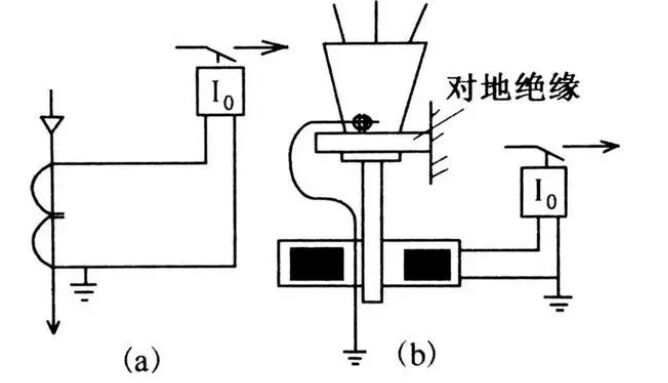
On the overhead lines that use cables to lead out or lead out through cables, zero-sequence current transformers that are set outside the cables are widely used to form grounding protection, as shown in the following figure:
The primary winding of the zero-sequence current transformer is made between the power cables passing through the core window of the zero-sequence current transformer. When it is normal or a phase-to-phase short circuit occurs, the secondary winding of the zero-sequence current transformer only outputs unbalanced current, and the protection does not operate. When a single-phase ground fault occurs, a zero-sequence magnetic flux appears in the core of the zero-sequence current transformer, which generates an induced potential on the secondary winding, so a current flows through the current relay. When the current flowing through the current relay is greater than When the operating current is activated, the relay operates.
Installation of zero-sequence current transformer: When installing zero-sequence current transformer, attention should be paid to insulate the iron bracket fixing the cable head from the ground, and pass the ground wire of the cable head through the iron core window of the zero-sequence current transformer. grounded. The reason is that some power cables have lead cladding, aluminum cladding, and armoring. If the grounding wire of the cable head does not pass through the core window of the zero-sequence current transformer for grounding, the stray current in the ground is also conductive when the line is running normally. The flow on the cable sheath may cause zero-sequence current protection malfunction. When the line is single-phase grounded, the grounding current can be offset by the capacitive current in the cable sheath and the line, causing the protection device to refuse to operate.
Ⅴ. Why do power systems need line protection? What are the factors that may lead to line failure?
The power system needs line protection because various faults may occur in the power line during operation, and these faults may lead to instability of the power system, equipment damage, power outage and even safety risks. The role of line protection is to quickly detect these faults and take appropriate measures to ensure the safe, stable and reliable operation of the power system.
Factors leading to line failure:
1. Short circuit: Short circuit is one of the most common faults on power lines. It occurs when a direct short path is created between two or more wires, causing excessive current flow that can cause fires, equipment damage, and more.
2. Power quality problems: Power fluctuations and harmonics may affect power lines and cause abnormal faults.
3. Overload: Overload is a fault caused by the current exceeding the rated capacity of the line or equipment. Prolonged overloading may overheat the device, damage it or even cause a fire.