Ⅰ. Features of common line protection devices
1. Disadvantages of conventional relay protection:
Conventional relay protection is a combination of relays, such as overcurrent relays, time relays, intermediate relays, etc., through complex combinations to achieve protection functions, its shortcomings are as follows:
Conventional relay protection usually needs to set parameters according to the characteristics of power lines and systems, and these parameters are often not automatically adjusted with changes in system operating conditions after equipment installation. Therefore, for a power system with large changes or a system that needs to adapt to different working conditions, conventional relay protection may require frequent manual adjustments.Line Protection, Distribution, Backups
Conventional relay protection usually can only implement a single protection strategy, such as overcurrent protection, distance protection, etc. For complex fault situations, multiple protective devices may be required to work together to fully cover all possible fault types.
The service life is too short, because the aging of the relay coil directly affects the reliable operation of the protection.
It takes up a lot of space and is inconvenient to install. Many relay contacts are used, which greatly reduces the sensitivity and reliability of protection.
Maintenance is complicated, and it is difficult to find the problem after a failure. The workload of operation and maintenance is heavy, and the operating cost is about 60% higher than that of microcomputer protection.
The service life is too short, because the aging of the relay coil directly affects the reliable operation of the protection.
Debugging and overhaul are complex, and generally require a power outage to proceed, affecting normal production.
The operation is complicated and the reliability is low. In the past operating experience, it was found that there are two main reasons for many accidents: human reasons: accidents occur due to low automation level and complicated operation; the performance level of relay protection equipment is low, and secondary equipment cannot effectively detect faults.
The relay itself does not have a monitoring function. When the relay coil is short-circuited, it cannot be found without going to the scene.
The relay protection function is single, and it is necessary to install various meters to observe the real-time load.
Conventional protection is cheaper than microcomputer protection in terms of single set price, but the number of cables and screen cabinets used are large, especially the device life is short, and the operating cost (management costs, maintenance costs, etc.) is 60% higher than that of microcomputer protection. Still more than microcomputer protection.
2. Advantages of microcomputer protection
The protection exit, remote control exit, and local control exit of the microcomputer protection are all operated through a set of relays, so they are very reliable.
Microcomputer protection originally used a single-chip microcomputer, and the system has the functions of collection, monitoring, control, and self-inspection. A device can be used to discover the faults of the transmission line, the load and the operation of the device itself (when a certain fault occurs in the device itself, the microcomputer protection will present the fault through the self-test function), and the computer principle is used for remote control and monitoring.
Because the microcomputer protection uses various power logic operations to realize the protection function, it only needs to collect the current and voltage on the line, which can greatly simplify the wiring.
Microcomputer protection also has a communication function, which can transmit various data required by users to the monitoring center through the network for centralized scheduling.
The life of the microcomputer protection is long. Because the equipment is in a dormant state in normal state, only the program runs in real time, and the life of each component is greatly extended.
Microcomputer protection adopts photoelectric isolation technology to unify all collected electrical signals into optical signals, so that when there is a strong current attack, the device can establish its own protection mechanism.
The microcomputer protection has the function of clock synchronization, and uses the method of fault recording to record faults, which is convenient for fault analysis.
Microcomputer protection adopts multi-layer printed board and surface mount technology, so it has high reliability and anti-interference ability.
Microcomputer protection is more expensive than conventional protection in terms of single set price, but the number of cables used is very small, and there are few screen cabinets, especially the service life is as long as 25 years, and the operating costs (management costs, maintenance costs, etc.) are 60% lower than conventional protection. %, the comprehensive cost is still much less than conventional protection.
Ⅱ. Main types of line protection
1. Frequency protection: Frequency protection is used to monitor the frequency change of the power system. The abnormal frequency may be caused by generator out of step or other system problems.
2. Overcurrent protection: Overcurrent protection is one of the most common types of line protection. It judges whether there is a fault based on the magnitude of the current. When the current exceeds the set value, the protection system will trigger an action to cut off the faulty circuit. Overcurrent protection usually includes instantaneous overcurrent protection, time-limited overcurrent protection, etc.
3. Differential protection: Differential protection is a protection type that judges whether there is a fault by comparing the current at both ends of the line. If the current is unbalanced across the terminals, current is leaking between the terminals, possibly due to a fault. Differential protection is usually used in the protection of transformers, generators and other equipment.
4. Overvoltage protection: Overvoltage protection is used to detect abnormal voltage on the power line, such as excessive voltage. Overvoltage protection prevents overvoltage damage to equipment and may indicate area-wide power failures.
5. Distance protection: Distance protection is a type of protection that judges the fault location based on the relative relationship between the voltage and current of the power line. It usually calculates the impedance value of voltage/current according to the magnitude and phase angle of the current. When the impedance value exceeds the set value, the protection system will trigger the action.
6. Undervoltage protection: Undervoltage protection is used to detect abnormal voltage on the power line, such as too low voltage. Undervoltage protection prevents undervoltage damage to equipment and can indicate a power supply problem.
7. Difference frequency protection: Difference frequency protection is a special frequency protection that detects the frequency difference between two power systems in order to judge whether there is a fault or an accidental disconnection.
8. Directional protection: Directional protection judges the fault location according to the current flow direction. It is suitable for complex power systems and can distinguish which side of the line the fault occurs on.
9. Ground protection: Ground protection is used to detect ground faults in power lines or equipment. It can be divided into fixed value grounding protection and variable current grounding protection. The fixed value ground fault protection operates when the ground current reaches the set value, while the variable current ground fault protection judges the fault according to the rate of change of the ground current.
Ⅲ. Line protection configuration
1.10~35kV line: It plays the role of overcurrent protection and automatic reclosing. The basic configuration is differential protection, phase-to-phase distance protection, and directional phase overcurrent protection.
2.66kV line: It plays the role of phase-to-phase distance protection, directional phase overcurrent protection, and automatic reclosing. The basic configuration is the longitudinal differential protection.
3.110kV line: grounding and phase-to-phase distance protection, zero-sequence direction overcurrent protection, automatic reclosing. The basic configuration is the longitudinal differential protection.
4. 220kV line: grounding and phase-to-phase distance protection, zero-sequence direction overcurrent protection, automatic reclosing inconsistent protection, overvoltage protection. The basic configuration is the longitudinal differential protection.
Ⅳ. Function introduction of line protection
1. Distance protection
The distance element adopts the phase-comparison mho relay, that is, the phase-comparison equation is composed of the operating voltage Uop and the polarization voltage Up.
The general action equation of the phase-comparison distance relay is:
For ground distance relays, the working voltage is:
For phase-to-phase distance relays, the working voltage is:
The three-stage grounding and phase-to-phase distance relay in the device will be polarized by the positive sequence voltage when the positive sequence polarization voltage is high, otherwise it will enter the two-phase low voltage program. At this time, the memory positive sequence voltage is used as the polarization voltage. The non-memory positive-sequence voltage is used as the polarization voltage. During the fault period, the positive-sequence voltage is mainly formed by the sound phase voltage. The positive-sequence voltage is consistent with that before the fault, and the relay has good directionality.
2. Zero sequence reactance
Operating Voltage:
Polarization voltage:
The phase comparison equation is:
3. Low voltage distance relay
The protection uses the memory voltage as the polarization voltage, and judges whether the action condition is satisfied by comparing the phase relationship between the polarization voltage and the working voltage.
Operating Voltage:
Polarization voltage:
Ⅴ. In power line protection, what is differential protection?
Differential protection is a common power line protection method, which is used to detect faults in power systems, especially in transformers, generators and other equipment.
Differential protection compares the current flowing into and out of a device to determine if there is a fault and where it is located. The basic principle is that when the current is normally balanced between the equipment, the sum of the current flowing into and out of the equipment should be close to zero, and when a fault occurs, the imbalance of the current will trigger the action of the protection device.
The main features and principles of differential protection:
1. Current balance detection: Under normal operating conditions, the current should be balanced between devices, that is, the differential current is close to zero. But if a fault occurs, such as a short circuit or a winding to ground, the imbalance in the currents will cause the differential current to increase, which is what differential protection is concerned with.
2. Set value and action logic: The differential protection device will set a set value of differential current, if the differential current exceeds this set value, the protection device will operate
3. Differential current calculation: In differential protection, the current of the equipment (usually the winding current of the transformer or generator) is measured through the current transformer (CT) when entering the equipment and leaving the equipment, and then calculates the current of the two differential current. The differential current is equal to the current entering the device minus the current leaving the device.
4. High sensitivity: Differential protection is very sensitive to fault detection, because faults will cause current imbalance, which will lead to increase of differential current.
5. Scope of application: Differential protection is usually applied to the protection of transformers, generators and other equipment, because the winding current of these equipment is relatively large and stable, which is convenient for differential current detection.
Ⅵ. Future development trends in the field of line protection
1. Intelligent protection: With the development of artificial intelligence and machine learning technology, intelligent protection will become an important direction in the future. The intelligent protection device can automatically optimize the protection strategy by learning the operation mode and fault conditions of the power system, and improve the adaptability to complex faults and changing conditions.
2. Mixed protection strategy: Future line protection may use a combination of multiple protection strategies to achieve more comprehensive fault detection and protection. For example, combining distance protection, differential protection and directional protection to improve the reliability and accuracy of fault detection.
3. Comprehensive protection system: In the future, the line protection system will be more comprehensive, not only including a single protection device, but also covering communication, monitoring, control and other functions to achieve a higher level of line protection and system management.
4. Open system: An open system can promote the interaction and integration of protection devices from different manufacturers, achieving a greater degree of interoperability and flexibility.
5. Digital technology: Digital technology will continue to affect the field of line protection. Digital protection devices can collect, process and analyze power system parameters more accurately, and improve the accuracy and speed of fault detection.
6. Virtualization technology: Virtualization technology can help build a virtual circuit protection test environment for simulating different fault scenarios for optimization and testing of protection strategies.
7. Communication technology: The line protection system will pay more attention to the application of communication technology to realize data exchange, remote monitoring and control between devices. The communication capability can improve the linkage and cooperative work ability of the protection device.
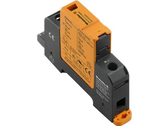
Ⅶ. Leakage protector
Leakage protector is a practical electrical product that is applied to home to protect users from leakage and electric shock. The surface of each protective socket is installed with: test and reset keys to detect the safety of line current. At the same time, it has the life self-test function, and can self-alarm when the life ends: generally reminded by the surface indicator light. The main function of the leakage protector is to cut off the power supply quickly when a leakage is detected in the circuit, so as to prevent the electric shock accident caused by the current passing through the human body, so as to ensure personal safety.
Unlike the overload protection of the miniature protective socket, the residual current device will trip between 0.5 times and 1 times the rated value. Household sockets usually use a 30mA residual current device, and the actual tripping current is 15mA to 30mA, while other larger ratings can only be used for upstream protective sockets.
type:
Residual current action protective socket with overcurrent protection: It is an integrated device that combines leakage and overcurrent protection, which can save space.
Residual current action protection socket: It is a protection socket with leakage protection function. RCCB is usually used in the sub-bar distribution box, and its downstream can be connected to multiple miniature protective sockets. Compared with installing multiple RCBOs, the cost of using a sub-bar design is lower. But when the RCCB trips, all downstream lines will lose power supply.
Applicable places:
Business equipment: vending machines, water spray car washing machines, ice cream machines, freezers, steam SPA machines, etc.
General household use: hair dryers, washing machines, drinking fountains, refrigerators, induction cookers, water heaters, electric cookers, dryers, range hoods, dehumidifiers, wet and dry vacuum cleaners, coffee machines, exhaust fans and other home appliances are applicable.
Other fortification equipment: pumping motors, various hand-held electric tools, etc. are available.