Ⅰ. Transformer material
Ⅱ. Basic principle of transformer
Ⅲ. Composition of Transformer
Ⅳ. How to maintain and maintain the transformer to ensure its normal operation and life?
Ⅴ. History of transformers
Ⅵ. What is the role and importance of the transformer in the power system?
Ⅶ. What are the cooling methods of the transformer? What are their pros and cons?
Ⅷ. Ideal Transformer
A transformer is a passive component that transfers electrical energy from one circuit to another circuit or circuits. A changing current in any coil of a transformer produces a changing magnetic flux in the transformer core, which induces a changing electromotive force (EMF) on any other coil wound on the same core. Electrical energy can be transferred between separate coils without a metallic (conductive) connection between the two circuits.
The main components of the transformer include two or more sets of coils (primary coils, secondary coils) and iron cores, which are used to increase or decrease the voltage of alternating current, change impedance and separate circuits.
Transformers are used to change the AC voltage level, this type of transformer is known as a step-up or step-down type to increase or decrease the voltage level respectively.
Transformers are also used to provide galvanic isolation between circuits and to couple stages of signal processing circuits. A wide variety of transformer designs are encountered in electronics and power applications. Transformers range in size from radio-frequency transformers that are less than a cubic centimeter in size to devices weighing hundreds of tons for interconnecting power grids.
A transformer is a device that uses the principle of electromagnetic induction to change AC voltage. In electrical equipment and wireless circuits, it is often used for raising and lowering voltage, matching impedance, safety isolation, etc. In a generator, whether the coil moves through a magnetic field or the magnetic field moves through a stationary coil, an electric potential is induced in the coil.
Ⅰ. Transformer material
The winding material is the most important thing to pay attention to when installing a transformer. Devices made of different materials play different roles. For winding transformers, due to the special structure of the device, materials such as enameled wire, yarn-covered wire, silk-covered wire, and paper-covered wire are selected for installation, which can exert good electrical and thermal conductivity, and the superior corrosion resistance also enhances the circuit. stability.
From the perspective of existing transformer products, winding materials in transformer installation generally include: iron core materials, insulating materials, impregnating materials, etc., and installers must choose according to the actual situation.
1. Iron core material
The transformer uses the principle of electromagnetic induction to regulate the current value and voltage value, and the iron core is the core component of the transformer, and its material condition determines the regulation function of the transformer. The iron core material is best to add silicon to the iron sheet, so as to reduce the electric and heat conduction effect of the low steel sheet, and avoid the increase of energy consumption after the device is running.
The power industry standard stipulates that the magnetic flux density of the silicon steel sheet should be controlled within the effective range, for example, the magnetic flux density of the black iron sheet is 7000, and the low silicon sheet is 10000, etc.
The installation site can be selected according to the actual situation.
2. Insulation material
The accident rate of transformer installation and operation continues to increase. Considering the safety issues during the transformer installation process, it is necessary to pay attention to the selection of insulating materials to protect the normal operation of other equipment in the system. At present, many transformers have been equipped with insulating components, such as gaskets, insulating appliances, etc., but there are still safety risks due to improper human operation. Transformer installation needs to enhance its insulation performance from the aspects of isolation between layers of coil frame and isolation between windings.
3. Dipping material
Impregnation treatment is the final process of winding materials. The main purpose is to improve the mechanical properties, electrical properties and insulation properties of materials, and avoid various safety accidents in later use. After selecting the winding material, the installer should paint the impregnated material and set an insulating layer on the surface of the material. The more commonly used paint material is cresol varnish, which can play a better safety role after painting and prolong the service life of transformer equipment.
Ⅱ. Basic principle of transformer
A simple single-phase transformer consists of two conductors. When some indeterminate current (such as alternating current or pulsed direct current) passes through one of the conductors, a changing magnetic field will be generated. According to the principle of electromagnetic mutual inductance, the changing magnetic field will cause a potential difference in the second conductor. If the second conductor is part of a closed circuit, the closed circuit will produce a current. Electricity is then transmitted.
In a common transformer, the electrical conductors involved are coils of (mostly copper) wire, because the magnetic field produced by a coil is much greater than that of a straight wire. The principle of the transformer is that a changing voltage is applied to the primary coil to generate a changing magnetic field on the magnetic core, thereby exciting other coils to generate a changing electromotive force.
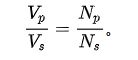
As for the current or voltage ratio between the two sides of the transformer, it depends on the number of turns of the two circuit coils. The side with more turns has higher voltage but lower current, and vice versa. If factors such as leakage are excluded, the voltage ratio of the two sides of the transformer is equal to the ratio of the coil turns of the two sides, that is, the voltage is proportional to the number of turns. formula:
According to the ampere-turn balance, the interlinkage magnetomotive force on both sides of the transformer must be equal, the formula:
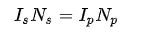
VP is the voltage of the input side; VS is the voltage of the output side; NP is the number of coil turns of the input side; NS is the number of coil turns of the output side.
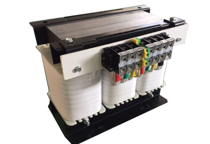
Ⅲ. Composition of Transformer
Transformers typically include:
A circle of metal core: it couples the magnetic field of mutual induction with the coil. Transformers generally operate at low frequencies, with wires wound around an iron core in windings. Although some energy is lost in the iron core, it helps to confine the magnetic field inside the transformer and improve efficiency. Power transformers are divided into core structure and shell structure according to the structure of the core and winding, and according to the number of branches of the magnetic flux (three-phase transformers have 3, 4 or 5 branches). Their performance varies.
Two or more coils: to input alternating current and output induced current.
1. Insulation: Insulating materials are required between the windings and between the windings and the core to prevent electrical short circuits and insulation failures. The insulating material can be insulating paper, insulating varnish, insulating tape, etc.
2. Core:
Sheet steel core: Transformers usually use a silicon steel core as the main magnetic circuit. This results in a more concentrated magnetic field in the coil and a more compact transformer. The iron core of the power transformer must be designed to prevent the saturation of the magnetic circuit, and sometimes it is necessary to design some air gaps in the magnetic circuit to reduce saturation. The actual transformer core is made of very thin silicon steel sheets with high resistance. This can reduce the loss and heat generated by each layer of eddy currents. There are similarities between power transformers and audio circuits. Typical layered iron cores are generally in the shape of E and I letters, called "EI transformers".
One problem with this type of core is that residual magnetism remains in the core after power is removed. When power is applied again, the residual magnetism will temporarily saturate the iron core. For some transformers with a capacity exceeding hundreds of watts, the inrush current can cause the main fuse to blow if no current limiting circuit is used. More seriously, for large power transformers, inrush currents can cause deformation of the main winding.
Solid core: In high-frequency circuits such as switching power supplies, powdered iron cores of ferromagnetic materials with high permeability and resistivity are sometimes used. At higher frequencies, insulators and magnetically permeable materials are required, and various ceramic materials called ferrites are common. Some transformer cores in some FM radio circuits use adjustable cores to match the coupling circuit to achieve resonance.
3. Coil: The coil is composed of electromagnetic wires, which are used to surround the iron core, so as to generate a magnetic field by electrification, or generate an induced current through the magnetic field.
4. Iron core: The iron core is the main structural part of the transformer, usually composed of laminated silicon steel sheets. The core provides a closed magnetic circuit that enables both the primary and secondary windings to couple to each other through a magnetic field.
5. Cooling system: Large transformers usually require a cooling system to control the temperature to prevent overheating. The cooling system can be in the form of air cooling, oil cooling, air cooling, etc.
6. Oil level gauge and thermometer: Oil-immersed transformers are usually equipped with an oil level gauge and thermometer to monitor the level and temperature of the oil to ensure the transformer is working properly.
7. Oil tank and cooling oil: Oil tanks are usually used in oil-immersed transformers, where the windings are soaked in insulating oil. This oil not only provides insulation but is also used in cooling to control temperature.
8. Protection and control equipment: These equipment can include temperature sensors, insulation monitoring equipment, voltage and current sensors, etc., which are used to monitor the status and performance of the transformer and trigger protective measures when necessary.

标签:Transformers

