中文

Select Language

English 中文 Deutsch Français español Português
Tanssion > 博客 > 开关 > The working principle and classification of the switchs

The working principle and classification of the switchs

作者: Tanssion 日期: 2023-08-07 点击量: 0

Ⅰ. Working principle of the switch
Ⅱ. Contact bounce of the switch
Ⅲ. Contact configuration of the switch
Ⅳ. Classification of switches
Ⅴ.What is the working principle of a switch?
Ⅵ.What are the classification of switches?
Ⅶ.What are the classification of switches according to construction?
Ⅷ.What are the 4 basic switches?
Ⅸ.What is the working Principle of the circuit?
X.What are the principles of two way switch?


Ⅰ. Working principle of the switch


The working principle of the switch is basically to realize the opening and closing of the circuit according to the electrical and mechanical principles. Different types of switches work differently.


The working principle and classification of the switchs


1. Delay switch: close the power switch K2, and then press the button switch K1. At this time, the crystal diodes V1 and V2 are turned on, and the relay is closed. At the same time the power supply charges the capacitor C. When K1 is disconnected, because C has been charged, it will discharge through R and V1V2, thereby maintaining the transistor to continue to conduct, and the relay is still closed. After a period of discharge, when the voltage between the two poles of C drops to a certain value, it is not enough to keep the triode conducting, and the relay is released. The time interval from K1 disconnection to relay release is called delay time. It depends on the size of R and C.


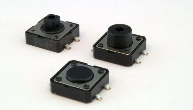
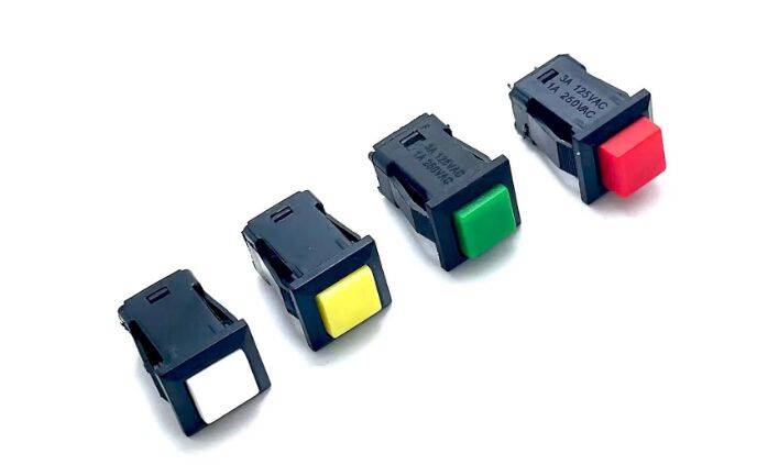
2. Manual switch: The most common type of switch, such as a push button switch or toggle switch, is manually operated to open or close a circuit. When a lever or button is pressed or toggled, the mechanical structure inside changes the position of the contacts, opening or closing a circuit.


3. Smart switch: Smart switches are usually connected wirelessly or through a network, and the on-off state can be remotely controlled through a smartphone or other devices.


4. Pressure switch: The pressure switch will open and close the circuit according to the pressure change of the external object. When the external pressure changes, the internal mechanical structure of the switch triggers the opening and closing of the circuit.


5. Hall effect switches: These switches use the Hall effect to switch circuits on and off by sensing an external magnetic field. Under the action of the magnetic field, the Hall element generates a voltage difference, which triggers the operation of the switch.


6. Temperature switch: The temperature switch will open and close the circuit according to the change of the surrounding temperature. The internal temperature sensing element will trigger the operation of the switch when a certain temperature is reached.


7. Automatic switch: Some switches have automatic features, such as infrared sensor switches. These switches automatically open and close circuits based on received signals, such as infrared light.


8. Photosensitive switch: The photosensitive switch will open and close the circuit according to the change of the intensity of light. When the outside light reaches a certain level, the light sensor triggers the operation of the switch.


Ⅱ. Contact bounce of the switch


Contact bounce is a common problem with mechanical switches and relays. The contacts of switches and relays are usually made of resilient metal. When the contacts are knocked together, the contacts are under the action of the impulse force and the elastic force,causing the bouncing part to occur one or more times before the contacts stabilize. The result is a rapid pulse of current instead of a definite transition from zero to full current. This effect is usually not important in power circuits, but it can cause problems in some analog or logic circuits because the fast switching response is fast enough to cause the circuit to mistake the switching pulses for data flow.


The effect of contact bounce can be eliminated by using a mercury switch, but this method is not often used because of the hazard of mercury leakage. Another approach is to add a low-pass filter to the contact circuit to reduce or eliminate composite pulses. In digital systems, anything can be controlled by taking multiple samples of the contact state or imposing a delay so that the contact bounce settles before the desired contact input state. One way is to implement it with a Single Pole, Double Throw switch, which is to use an SR latch. [3] These methods are debouncing circuits.


The term debounce is derived from this, and it appears in the software development industry to describe a rate-limiting or thottling the frequency of an implementation method that eliminates switch bounce.

The working principle and classification of the switchs


Ⅲ. Contact configuration of the switch


The contact configuration of a switch refers to the connection method and number of contacts inside the switch, which determine how the switch affects the on-off state of the circuit when it is operated.


A set of junctions is closed when two junctions are in contact with each other, allowing electrons to flow from one junction to the other. The open of a group of contacts means that the two contacts are not in contact with each other, and electrons are not allowed to pass through under normal voltage.


Some contacts are open under normal conditions, and need external force or other signals to become closed. This kind of contact is called "Normal Open" contact or A contact, also known as Break. Other contacts with opposite characteristics (closed circuit under normal circumstances, and need external force or other signals to become open circuit) are called "Normal Close" contacts, or B contacts, also known as Make.


The above-mentioned abbreviations often appear in wiring diagrams—although there are many diagrams that directly use different symbols to distinguish the two—in order to indicate the contact characteristics to be used, which is helpful for wiring, analysis and problem diagnosis. Some switches have the above two kinds of contacts at the same time, so you can choose to conduct a normally closed contact or a normally open contact. At this time, there is usually a common contact. This common point is called "C contact".


"Closed first, then opened" contact, because when switching, the contact to be switched is first turned on, and then the original contact is disconnected.


"Open first, then close" contact, because when switching, the original contact is disconnected first, and then the contact to be switched is turned on.


Most of the switches use the instantaneous power conversion after spring preloading, so that the contacts can be switched quickly when switching.


It is necessary to decide which contact to use according to the application: for example, a switch to switch two sets of power sources may need to use a "first open and then close" contact to avoid short circuit caused by two power supplies being connected at the same time.


Common Switch Contact Configurations:


1. Single Pole Single Throw (SPST): This is the simplest contact configuration. It has a contact that turns a circuit on or off.


2. Single Pole Double Throw (SPDT): This configuration has one contact but can switch between two different circuits, when one is open the other is closed and vice versa.


3. Double Pole Single Throw (DPST): This configuration has two contacts that can simultaneously open or close two separate circuits.


4. Multiple poles and multiple Throws: In some complex applications, more contact configurations may be required. For example, Tripolar Double Throw (TPDT), etc.


5. Bipolar Double Throw (DPDT): This configuration has two contacts that can switch between two different pairs of circuits at the same time.


6. Multi-position switch: In addition to the common two positions (on and off), there are also some multi-position switches that can switch between multiple positions.


Ⅳ. Classification of switches


1. Proximity switch: Proximity switch is also called non-contact stroke switch. In addition to stroke control and limit protection, it is also a non-contact detection device, which is used to detect the size of parts and speed measurement, etc., and can also be used for frequency conversion. Counter, frequency conversion pulse generator, liquid level control and automatic connection of processing programs, etc. Features include reliable operation, long life, low power consumption, high reset positioning accuracy, high operating frequency, and adaptation to harsh working environments.


Main uses of proximity switches: Proximity switches are widely used in aviation, aviation, aerospace technology and industrial production. In daily life, such as automatic doors of hotels, restaurants, garages, and automatic hot air fans are used. In terms of security and anti-theft, important places such as data files, accounting, finance, museums, and vaults are usually equipped with anti-theft devices composed of various proximity switches. In measurement technology, such as length and position measurement; in control technology, such as displacement, speed, acceleration measurement and control, a large number of proximity switches are also used.


Common proximity switches are:


Capacitive proximity switches: The measurement of the switch is usually one plate that makes up the capacitor, while the other plate is the housing of the switch. This case is usually grounded or connected to the case of the device during the measurement. When an object moves towards the proximity switch, regardless of whether it is a conductor or not, due to its proximity, the dielectric constant of the capacitor will always change, thereby changing the capacitance, and the state of the circuit connected to the measuring head will also change accordingly. Change, which can control the switch on or off.


Photoelectric proximity switch: A switch made of photoelectric effect is called a photoelectric switch. Install the light-emitting device and the photoelectric device in the same detection head according to a certain direction. When a reflective surface (object to be detected) approaches, the photoelectric device will output a signal after receiving the reflected light, so that it can "sense" that an object is approaching.


Eddy-current proximity switch: This switch is sometimes called an inductive proximity switch. It uses a conductive object to generate an eddy current inside the object when it is close to the proximity switch that can generate an electromagnetic field. The eddy current reacts to the proximity switch, causing the internal circuit parameters of the switch to change, thereby identifying whether a conductive object is approaching, and then controlling the switch to be turned on or off.


Hall proximity switch: It is a magnetic sensitive element. A switch made of a Hall element is called a Hall switch. When a magnetic object moves close to the Hall switch, the Hall element on the detection surface of the switch will cause the state of the internal circuit of the switch to change due to the Hall effect, thereby identifying the presence of a magnetic object nearby, and then controlling the switch to be turned on or off. The detection object of this proximity switch must be a magnetic object.


Pyroelectric proximity switch: A switch made of an element that can sense temperature changes is called a pyroelectric proximity switch. This kind of switch is to install the pyroelectric device on the detection surface of the switch. When an object with a different temperature from the environment approaches, the output of the pyroelectric device will change, so that the object can be detected.


2. Delay switch: Delay switch is a switch with time control function, it will have a predetermined delay time after operation, and then it will switch state. The delay switch is a kind of switch that uses the electronic component relay installed in the switch to delay the switch circuit. The delay switch is divided into voice-activated delay switch, light-activated delay switch, touch-activated delay switch and so on.


3. Classified by purpose


Toggle Switches: is a common manually operated switch, usually used to open or close a circuit. It looks like a small toggle button that can be manually flipped or toggled to change the state of the circuit. Its characteristic is that it needs to change the state of the circuit through manual operation. It usually has two operating positions: open and closed; once toggled in a particular position, the toggle switch remains in that position until manually toggled again; toggle switches usually have a relatively simple mechanical structure consisting of several contacts and a Composition of switching devices.


Recording and playback switch: refers to a switch used to switch equipment or equipment components between recording and playback modes. This type of switch is common in audio equipment, video equipment, and some recording equipment. The function of the recording and playback switch is to switch the signal path between recording and playback to achieve different operations. In record mode, the input signal is routed to recording media for recording. In playback mode, the signal read from the recording medium is sent to a speaker or other output device for playback.


Power switch: It is a switch used to control the power supply of electrical equipment, which is used to turn on or off the power of the equipment. Typically, a power switch is used to switch a device from a standby or off state to an active state, or vice versa. Its characteristic is to control the power supply of the equipment, that is, to connect or disconnect the power supply to the equipment. Power switches can also be used to protect equipment and save energy. By turning off the power, you prevent energy consumption and potential failure when the equipment is not in use.


Control switch: It is a switch used to control the operation of circuits or equipment. It can be used to open or close electrical circuits to realize the control of equipment. The function of the control switch is to open or close the circuit when necessary, so as to control the operation or stop of related equipment. For example, a light switch in a home, a start button on a machine, or even various control buttons and switches in an industrial automation system can all be called control switches.


4. Classified by structure

Key switch: A key switch is a special type of control switch, usually a manually operated switch that controls the opening and closing of a circuit by pressing a button. Its feature is that the circuit state can be changed by manually pressing the button, the operation of the key switch is short, and it will return to its original position immediately after pressing the button.

Pushbutton Switch: A pushbutton switch is a common type of manually operated switch that turns a circuit on or off by pressing a button. Pushbutton switches are often used where manual control of electrical equipment, machinery, lighting, etc. is required. Push button switches require manual pressing of a button to change the state of a circuit. Once a button is pressed, it remains pressed until pressed again or reset.

Micro switch: A micro switch is a small manually operated switch, usually consisting of a movable lever and a set of electrical contacts. Micro switches require manual or object motion to trigger operation, usually a light touch or push. Typically, the operation of a microswitch is transient, triggering a circuit state change only when the lever is pressed or released.

5. Classified according to the number of switches

Single control switch: A single control switch is a common electrical switch that is used to control a single electrical device or lighting device. This type of switch is usually used to turn on or off a specific circuit in one position. The main function of the single control switch is to control the opening and closing of a single device or light in one position. It is usually by manual operation, such as pressing or switching, to change the state of the circuit.
Multi-control switch: A multi-control switch is a device used to control multiple switches of a circuit or device at the same time. A multi-control switch includes multiple operation buttons, which can be distributed in different positions, and are usually connected to the same circuit by wires.

Double control switch: It is a two switch system used to control an electrical device or lighting device. These two switches are usually installed in different positions and can control the same circuit simultaneously or separately.

Touch switch: It is an electrical switch that does not require a physical button or switch, and it realizes the opening and closing of the circuit by directly touching the sensing surface. Touch switches do not require traditional buttons or switches, but touch a specific area to trigger a change in the state of a circuit. The sensitivity of the touch switch can be adjusted according to the design and settings of the device.

Inductive switch: also known as a trigger switch or a sensor switch, is a switching device that can control a circuit by sensing physical or electromagnetic changes in the external environment. Common sensor switch types include temperature sensor switch, light sensor switch, proximity sensor switch, infrared sensor switch, sound sensor switch, motion sensor switch, etc.

Smart switch: It is a switch device with intelligent functions, which enables users to remotely control, automate scheduling or integrate with other smart devices by connecting to the network or using built-in smart technology.

6. Other categories

Rotary switch: It is a common electronic switching device that controls the switching state of a circuit or adjusts the function of a device by rotating it. Rotary switches typically have an axis of rotation that the user can rotate to change the state of the switch or select a different option. Rotary switches can be of various types, including single-pole single-position switches, multi-position switches, rotary switches, etc. They can choose different operation modes and functions according to the needs. Rotary switches are often used to select different modes, gears, volume, brightness, etc. This use is often seen in audio equipment, dimming lights, televisions, and more. It can also be used to control the switching state of circuits, such as turning electrical equipment on or off. It is used in household, industrial and automotive fields.

Magnetic Reed Switch: Also known as a magnetic reed sensor or reed switch, is a magnetic reed-based switching device that is commonly used to detect the proximity or distance of an object. This switch triggers the switching action of the circuit by sensing the change of the external magnetic field. A magnetic reed switch operates based on the attractive force of a magnetic reed and a change in the magnetic field. When the nearby magnetic field changes, the magnetic reed shifts, triggering the switch. It consists of one or more magnetic reeds, a fixed magnet and a movable magnet. Magnetic reed switches typically have two states: engaged and disengaged. When the external magnetic field exists, the magnetic reed will pull in, making the switch closed; when the external magnetic field disappears, the magnetic reed will separate and the switch will open.

Thumbwheel switch: Also known as a rotary switch or selector knob, is a switching device used to select different modes, gears, or settings. It is usually a rotatable knob that can be turned to change the function or state of the device.

Slide switch: also known as slide switch or slider switch, is a common electronic switch device that controls the switching state of a circuit or adjusts the function of a device by sliding operation. Slide switches typically have a slideable slider that can be slid to change the state of the switch or select different options. You can change the state of the switch or select a different option by sliding the slider.

A slide switch may have multiple positions or options, and the slider can be moved to a specific position to select the appropriate function.

Keyboard switch: It is a common electronic switch device, usually used on computer keyboards or other similar input devices. It allows the user to trigger the switching action of the circuit by pressing a button, thereby generating a specific input signal. Keyboard switches can have different types of keys, such as standard keys, function keys, arrow keys, etc., and each key has different functions and uses.

DIP switch: is an electronic component typically used for manual configuration and settings on a circuit board. It consists of a series of switches, each representing a binary option that can be turned on or off to select a specific configuration or setting. DIP switches are usually in the form of a dual in-line package that fits into a standard DIP socket. Each switch has a pair of pins that connect to pads on the board.

DIP switches are usually used to set hardware parameters, such as address lines, data lines, mode selection, etc. on the circuit board. In some cases, DIP switches can be used as a replacement for jumpers for making circuit configurations and adjustments.

The working principle and classification of the switchs

Tact switch: It is a switch device that does not need to be pressed hard. It allows the switching action of the circuit to be triggered by lightly touching or pressing the switch panel or button, thereby generating a specific operation, function or signal. Unlike traditional mechanical push switches, the tact switch does not need to be pressed hard, it only needs to be touched lightly to trigger. Some tact switches may have a backlight feature that illuminates when the switch is touched. In addition, the indicator light can also be used to display the switch status.

Selector switch: also known as knob selector switch, rotary selector switch, is an electronic switch device that is usually rotated to select different functions, modes, gears or states. The selector switch selects different options by rotating the knob, and the function or mode can be switched by rotating the knob to a specific position. Selector switches are often equipped with tick marks, numbers, or markings to show the currently selected option. A selector switch usually consists of a housing, knob, turning shaft, etc., and its mechanical construction may vary by manufacturer and application.

Ⅴ.What is the working principle of a switch?

The function of an electric switch is to regulate the current between the load and source of power. The power source is the electrons that push through the circuits. The voltage is the quantity of force or pressure applied by the power source.

Ⅵ.What are the classification of switches?

There are four main types of switches— single pole single throw, single pole double throw, double pole single throw, or double pole double throw.

Ⅶ.What are the classification of switches according to construction?

The types of switches are classified into four types namely: SPST (Single Pole Single throw) SPDT (single pole double throw) DPST (double pole, single throw)

Ⅷ.What are the 4 basic switches?

Basic Switches come in four sizes: General-purpose, Miniature, Subminiature and Ultra Subminiature, depending on the device and scale of the equipment they are to be used in.

Ⅸ.What is the working Principle of the circuit?

Under normal conditions – closed circuit – these contacts are touching each other, allowing the flow of electric current. These moving contacts are held together thanks to mechanical pressure exerted by another mechanism – a spring or compressed air, for example.

X.What are the principles of two way switch?

The L1 terminals of both the switches are connected to line (or phase or live) of the AC Supply. The L2 terminals of both the switches are connected to one terminal of the light bulb, while the other terminal of the light bulb is connected to the neutral of the AC power supply.


标签:

常见问题解答

1、How to choose the switch type suitable for a specific application?
The first step is to define what the application is and what type of operation and control it requires. Is it a simple on/off operation that requires a switch, or a complex operation such as multiple gears, mode switching, rotary selection, etc. According to the application requirements, to determine the operation mode of the switch, it is necessary to press, rotate, slide, tap, touch, etc. to trigger the switch action. Consider what environment the switch will be used in, and whether it needs to be dustproof, waterproof, corrosion-resistant, etc. For example, outdoor equipment may require switches that are more durable and resistant to dust and water.
2、What are the common applications of electrical switches in household appliances?
Common applications include: light switches, power tools, induction cooker, gas range controls, washer and dryer controls, air conditioning controls, humidifiers and purifiers, etc.
3、How to detect whether the switch is working properly?
First, check that the switch looks good, with no obvious physical damage or wear. Make sure the switch housing is complete with no loose parts. Conduct an operation test of the switch, that is, check whether the switch action is triggered by pressing, rotating, sliding or tapping. Pay attention to whether you need to use force and whether you feel stuck. Perform a continuity test with a multimeter in resistance measurement mode to check that the contacts of the switch are connected properly. With the switch closed, the resistance between the contacts should be zero or close to zero. In the open state of the switch, the resistance should be infinite. For complex switches, such as selector switches or multi-position switches, test each position or option for proper functioning to ensure the desired function is switched.
4、 What is the difference between a switch and a circuit breaker?
Switches are used to open and close circuits, thereby controlling the flow of electricity. It can cut off or connect current in the circuit and is the basic element of controlling electrical equipment. A circuit breaker can also be used to cut and connect circuits, but it also has the functions of overload protection and short circuit protection. When the current in the circuit exceeds the rated value or a short circuit occurs, the circuit breaker will automatically cut off the circuit to prevent equipment damage or fire.

留下评论

相关文章

热门零部件

#10FWZ

#10FWZ

#292KNAS-T1028Z

#292KNAS-T1028Z

#458PT-1566=P3

#458PT-1566=P3

#458PT-1720=P3

#458PT-1720=P3

#458PT-2002=P3

#458PT-2002=P3

#458PT-2078=P3

#458PT-2078=P3

#617PT-2038=P3

#617PT-2038=P3

#617PT-2270=P3

#617PT-2270=P3

热门标签

PMIC Audio Products Logic Interface capacitors linear controllers embedded Line Protection drivers amplifiers Distribution Backups wireless modules memory converters Battery Products sensors filters relays Switches distribution analog Clock timing voltage diodes speakers Batteries Rechargeable battery regulators Fiber Optic Cables Cable Assemblies routers microcontroller Backups audio Magnetics - Transformer Inductor Components cables Electric Double Layer Capacitors (EDLC) Supercapa inductors transformer optoelectronics potentiometer resistors switching management special digital purpose signal Discrete Semiconductor Ceramic Capacitors semiconductor cable Alarms equipment resonators oscillators crystals kits accessories isolators motors RF Transformers monitors comparators specialized programmable microcontrollers FPGAs Data Acquisition application specific gates inverters Buffers Transceivers dividers Sensor decoders microprocessors microprocessor DC video circuit protection microphones PCB Integrated Circuits (ICs) PMIC - Lighting Memory Cards SSDs HDDs Wires Tantalum Capacitors Transducers LEDs Battery Chargers 4G Ballast Controllers Vacuum Tubes Transistors - Bipolar (BJT) - Single counter integrated circuits Guitar Parts Buzzer Elements transducers circuit Computer Equipment Piezo Benders boxes Magnetics enclosures racks Buzzers wires and Sirens wire Buzzers and Sirens inductor components connectors interconnects CR2450 LR44 Embedded Computers TXS0108EPWR fans SS14 thermal UA741CP RC4558P hardware TNY268PN fasteners MJE2955T UC3842AN TOP245YN coils SN6505BDBVR chokes BD139 controls ATMEGA328-PU automation NE5532P identification barriers signs labels protection inductor educational networking resistor powersupply power supply prototyping fabrication desoldering soldering ESD static Tapes adhesives materials Test measurement Tools Uncategorized Specialized ICs voltage Regulators contro thermal Management motor laser full half switchers batteries translators shift latches flip flops voice playback serializers deserializers active synthesis PLDs clocks delay lines reference supervisors PoE correction lighting ballast hot swap energy metering specialty parity generators checkers FIFOs multipliers instrumentation UARTs terminators capacitive touch Modems ICs Encoders DSP Data acquisition front end timers synthesizers frequency regulator controller regula RMS power OR ideal LED gate display chargers configuration proms universal bus functions multiplexers multivibrators counters processing amps telecom repeaters splitters detector interfaces I/O expanders receivers CODECs system SoC CPLDs Complex amplifier IF RFID Oscillator Externally excited oscillator fuses switchs transistors shunt thyristor Oscillators Resonators Ballast Controllers Coils Chokes RF Filters RF/IF and RFID RF Amplifiers Battery Packs SAW Filters Mica and PTFE Capacitors Accessories Piezo Benders 1 222 sdsd ballasts starter SSD HDD Modules

热门博客