Ⅰ. Logic - Signal Switches, Multiplexers, Decoders
Ⅱ. Physical Characteristics of Logic - Signal Switches, Multiplexers, Decoders
Ⅲ. Electrical Characteristics of Logic - Signal Switches, Multiplexers, Decoders
Logic - Signal Switches, Multiplexers, Decoders
Logic gates are fundamental building blocks of digital circuits that process binary information. They are electronic devices that perform logical operations on one or more binary inputs and produce a binary output based on predefined rules. These gates include AND gates, OR gates, NOT gates, NAND gates, NOR gates, and XOR gates, among others.
Signal switches, multiplexers, and decoders are more complex components that can be constructed using logic gates. Let's explore each of them in more detail:
1.Signal Switches: Signal switches, also known as transmission gates or analog switches, are electronic components that can control the passage of signals through a circuit. They act as electronically controlled switches, allowing signals to flow or blocking them based on a control input. Signal switches are commonly used in both analog and digital circuits for tasks like routing signals, selecting paths, or isolating components.
2.Multiplexers: A multiplexer (MUX) is a digital circuit that combines multiple input signals into a single output signal. It selects one of the input signals based on a set of control inputs. Multiplexers are often used to transmit data from several sources to a single destination, enabling the selection of a specific input to be routed to the output. The number of inputs and control inputs determines the size of the multiplexer. Common examples include 2-to-1, 4-to-1, or 8-to-1 multiplexers.
3.Decoders: Decoders are circuits that convert coded inputs into multiple output lines. They are commonly used to decode binary information and activate a specific output line based on the input combination. Decoders are useful for tasks like address decoding, memory access, and control signal generation. Binary decoders are the most common type, with inputs representing binary numbers and outputs corresponding to the decoded values. For example, a 2-to-4 decoder converts a 2-bit input into four output lines, with only one line being active at a time based on the input value.
By utilizing these components, engineers can design complex digital systems that perform various functions. Signal switches, multiplexers, and decoders provide the flexibility and control necessary to handle data routing, selection, and decoding operations in digital circuits.
Physical Characteristics of Logic - Signal Switches, Multiplexers, Decoders
Signal switches, multiplexers, and decoders are electronic components used in digital circuits. Their physical characteristics can vary depending on the specific implementation and technology used. However, here are some general aspects related to their physical characteristics:
1.Integrated Circuits (ICs): Signal switches, multiplexers, and decoders are often implemented as integrated circuits. These ICs are small semiconductor chips that contain multiple electronic components, including transistors, resistors, and interconnections. ICs offer compactness, ease of manufacturing, and better performance due to their integration.
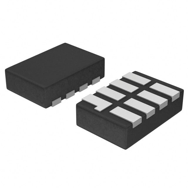
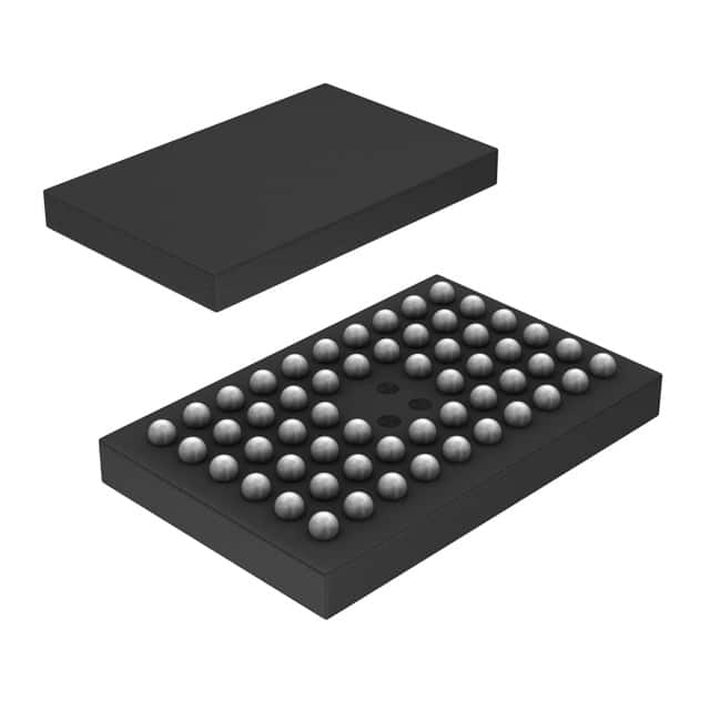
2.Package Types: Integrated circuits are typically packaged in various forms to protect the underlying silicon and provide electrical connections. Common package types include Dual Inline Package (DIP), Small Outline Integrated Circuit (SOIC), Quad Flat Package (QFP), Ball Grid Array (BGA), and many more. The choice of package depends on factors like pin count, size, thermal considerations, and manufacturing requirements.
3.Pin Configuration: The physical appearance of signal switches, multiplexers, and decoders is determined by the pin configuration of the integrated circuit. The pins on the package provide the electrical connections required for power supply, inputs, outputs, and control signals. The pin count can vary depending on the complexity and functionality of the component.
4.Technology: Signal switches, multiplexers, and decoders can be implemented using different technologies, such as Complementary Metal-Oxide-Semiconductor (CMOS), Bipolar Junction Transistor (BJT), or Field-Effect Transistor (FET) technologies. Each technology has its own advantages and trade-offs in terms of speed, power consumption, and voltage levels.
5.Voltage and Current Ratings: Signal switches, multiplexers, and decoders operate within specified voltage and current ranges. The voltage rating determines the maximum voltage that the component can handle, while the current rating indicates the maximum current it can safely carry. These ratings are important considerations for circuit design and ensuring proper operation.
6.Speed and Delay: Signal switches, multiplexers, and decoders have associated speed characteristics, often measured in terms of propagation delay. Propagation delay refers to the time taken for a signal to propagate through the component from input to output. Faster components can process signals more quickly, which is crucial for applications requiring high-speed data transmission or real-time operations.
It's important to note that the physical characteristics of these components can vary depending on the specific manufacturer, technology, and implementation details. Engineers consider these factors while selecting and integrating signal switches, multiplexers, and decoders into digital circuits, ensuring compatibility, performance, and reliability.
Electrical Characteristics of Logic - Signal Switches, Multiplexers, Decoders
The electrical characteristics of signal switches, multiplexers, and decoders play a crucial role in their proper operation and integration within digital circuits. Here are some key electrical characteristics to consider:
1.Supply Voltage (VCC): The supply voltage, often denoted as VCC, represents the voltage level required to power the component. It determines the operating voltage range within which the signal switches, multiplexers, and decoders function correctly. The datasheet of the specific component provides the recommended supply voltage range.
2.Logic Levels: Signal switches, multiplexers, and decoders typically operate with digital signals that have specific voltage levels to represent binary states. Common logic families include TTL (Transistor-Transistor Logic), CMOS (Complementary Metal-Oxide-Semiconductor), and LVCMOS (Low-Voltage CMOS). The logic levels, such as high (H) and low (L) voltage thresholds, define the voltage ranges at which the inputs and outputs are considered as logic high or logic low.
3.Input and Output Currents: The input current (Iin) and output current (Iout) characteristics are essential for ensuring proper signal integrity and driving capabilities. Input currents determine the amount of current required to maintain proper logic levels at the input pins, while output currents represent the maximum current that can be sourced or sunk at the output pins.
4.Power Consumption: Power consumption is an important consideration in digital circuits. It refers to the amount of electrical power consumed by the signal switches, multiplexers, and decoders during operation. It is typically measured in terms of power supply current (ICC) and is dependent on factors like the number of inputs, switching frequency, and technology used.
5.Propagation Delay: Propagation delay refers to the time it takes for a signal to propagate from the input of the component to its output. It is an important parameter that affects the overall performance and timing of the digital circuit. Shorter propagation delays are desirable for high-speed applications to minimize signal latency and ensure accurate data processing.
6.Fan-Out: Fan-out is the maximum number of inputs or outputs that a component can drive without significant degradation of signal quality. It indicates the capability of the component to deliver or receive signals to/from multiple destinations without causing voltage level distortions or excessive delays.
7.Noise Margin: Noise margin defines the tolerance of a logic circuit to electrical noise. It represents the difference between the minimum acceptable logic high voltage level and the maximum acceptable logic low voltage level. A larger noise margin provides better noise immunity and improves the reliability of the circuit.
These electrical characteristics are typically provided in the datasheets or specifications provided by the manufacturer. Engineers consider these parameters to ensure compatibility, performance, and reliable operation when incorporating signal switches, multiplexers, and decoders into digital circuits.

