Ⅰ. Data Acquisition - Analog to Digital Converters (ADC)
Ⅱ. Physical Characteristics of Data Acquisition - Analog to Digital Converters (ADC)
Ⅲ. Electrical Characteristics of Data Acquisition - Analog to Digital Converters (ADC)
Data Acquisition - Analog to Digital Converters (ADC)
Data acquisition involves the process of capturing, digitizing, and analyzing analog signals from various sources. Analog-to-Digital Converters (ADCs) are essential components of data acquisition systems as they perform the crucial task of converting analog signals into digital data that can be processed and utilized by digital systems. Here's an introduction to ADCs in the context of data acquisition:
Function and Operation: The primary function of an ADC is to convert analog signals into digital representations. It accomplishes this by sampling the analog signal at regular intervals and quantizing the sampled values into discrete digital codes. The ADC measures the amplitude of the analog signal and assigns a digital value that corresponds to that amplitude.
Resolution: ADCs have a specified resolution, typically expressed in bits. The resolution determines the number of possible output levels or quantization levels that the ADC can represent. A higher resolution ADC can represent smaller changes in the analog input and provide a more accurate digital representation.
Sampling Rate: The sampling rate of an ADC refers to the frequency at which it takes samples of the analog signal. It is measured in samples per second (or Hertz). The sampling rate must be chosen carefully to ensure that the ADC captures the necessary details of the analog signal without aliasing or loss of information. The Nyquist-Shannon sampling theorem states that the sampling rate should be at least twice the highest frequency component of the analog signal.
Input Range: ADCs have a specific input range that defines the minimum and maximum voltage levels that can be accurately converted into digital values. It is important to select an ADC with an input range that can accommodate the expected range of the analog signal being measured. Input ranges can be unipolar (positive only or negative only) or bipolar (positive and negative).
Conversion Time: The conversion time of an ADC is the time it takes to complete one conversion cycle, including sampling and quantization. Conversion time is determined by the ADC's internal circuitry and affects the speed at which the ADC can process incoming analog signals. It is an important consideration when dealing with time-sensitive applications.
Accuracy and Linearity: ADCs have associated accuracy and linearity specifications. Accuracy refers to how closely the digital output represents the actual analog input. Linearity refers to the ability of the ADC to provide a linear relationship between the analog input and the digital output. Nonlinearities can introduce errors in the conversion process and affect the overall accuracy of the data acquisition system.
Types of ADCs: There are various types of ADCs available, each with its own working principle, advantages, and limitations. Some common types include successive approximation ADCs, delta-sigma ADCs, pipeline ADCs, flash ADCs, and integrating ADCs. The choice of ADC type depends on factors such as required resolution, speed, power consumption, and cost.
Interface: ADCs provide digital outputs that can be interfaced with the digital system for further processing and analysis. The output can be in various formats, such as parallel, serial, or specific communication protocols (e.g., SPI or I2C). The choice of interface depends on the application requirements and the compatibility with the host system.
Applications: ADCs are utilized in a wide range of applications, including industrial automation, data acquisition systems, scientific instruments, medical devices, telecommunications, audio/video equipment, and more. They enable the conversion of real-world analog signals, such as voltage, current, temperature, pressure, or light intensity, into digital data for storage, analysis, and control within digital systems.
When selecting an ADC for a specific data acquisition application, it is important to consider factors such as resolution, sampling rate, input range, accuracy, linearity, power consumption, and interface compatibility. The choice of ADC greatly influences the overall performance, accuracy, and reliability of the data acquisition system.
Physical Characteristics of Data Acquisition - Analog to Digital Converters (ADC)
When considering the physical characteristics of Data Acquisition - Analog to Digital Converters (ADCs), several aspects come into play. Here are some key physical characteristics to consider:
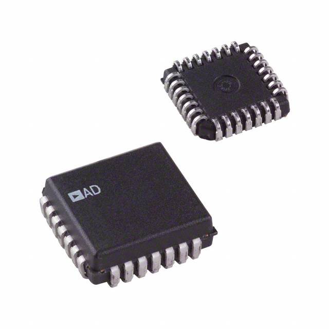
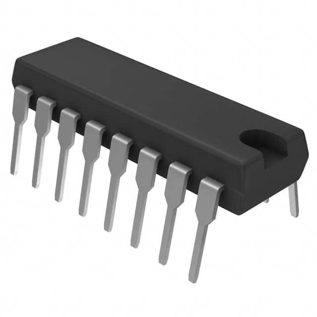
1.Package Type: ADCs are available in various package types, such as dual in-line package (DIP), quad flat package (QFP), small outline integrated circuit (SOIC), ball grid array (BGA), and chip-scale package (CSP). The package type determines the physical dimensions, pin count, and mounting method of the ADC.
2.Pin Count: ADCs have a specific number of pins that establish electrical connections with the surrounding circuitry. The pin count depends on the ADC's features, interface requirements, and package type. It is important to ensure that the ADC's pin count matches the available pin count on the printed circuit board (PCB) or the chosen interface.
3.Size and Form Factor: ADCs come in various sizes and form factors. The physical size is determined by the package type and can vary from small, surface-mount packages for compact designs to larger packages for higher pin count or specific applications. The form factor should align with the design constraints and available space in the system.
4.Mounting Method: ADCs can be mounted on a PCB using surface-mount technology (SMT) or through-hole technology (THT). SMT allows for compact and automated assembly, while THT requires holes in the PCB and manual soldering. The mounting method should align with the manufacturing capabilities and design requirements of the overall system.
5.Power Requirements: ADCs require a specific power supply to operate. The power supply voltage and current requirements are specified by the ADC manufacturer and should be considered to ensure proper functionality and integration within the system. It is important to provide a stable and clean power supply to minimize noise and interference.
6.Temperature Range: ADCs have specified temperature ranges within which they can operate reliably. The temperature range is important to consider, especially for applications in harsh environments or industrial settings where temperature extremes can be encountered. It ensures that the ADC performs accurately and withstands the operating conditions.
7.Environmental Considerations: Depending on the application and operating environment, ADCs may have specific environmental considerations. These may include humidity levels, moisture resistance, and protection against dust or contaminants. Compliance with relevant environmental standards or certifications may also be required.
8.ESD Protection: Electrostatic discharge (ESD) protection is crucial for ADCs, as they are sensitive to electrostatic charges. ADCs may incorporate built-in ESD protection measures, such as integrated diodes or shielding, to prevent damage from ESD events during handling, assembly, and operation.
9.Durability and Reliability: ADCs should be designed for durability and reliability to ensure long-term operation and accurate data acquisition. They undergo rigorous testing and validation to ensure their performance under various operating conditions, mechanical stress, and voltage ranges.
It is important to consult the datasheet and technical documentation provided by the ADC manufacturer for detailed information on the physical characteristics and specifications of a specific ADC model. Considering the physical characteristics alongside the functional requirements is crucial for seamless integration and optimal performance in a data acquisition system.
Electrical Characteristics of Data Acquisition - Analog to Digital Converters (ADC)
Electrical characteristics play a crucial role in the performance and compatibility of Data Acquisition - Analog to Digital Converters (ADCs). These characteristics determine the electrical behavior of the ADC and its interaction with the surrounding circuitry. Here are some key electrical characteristics to consider:
1.Supply Voltage: ADCs require a specific supply voltage to operate correctly. The supply voltage should be within the specified range provided by the manufacturer. It is essential to ensure that the power supply can provide the required voltage with sufficient stability and low noise levels.
2.Power Consumption: ADCs consume electrical power during operation. The power consumption depends on factors such as the ADC's architecture, resolution, sampling rate, and operational mode. It is crucial to consider the power consumption of the ADC and ensure that the power supply and system design can handle the requirements.
3.Input Voltage Range: ADCs have a specified input voltage range that determines the minimum and maximum voltages that can be accurately converted into digital values. It is important to select an ADC with an input voltage range that accommodates the expected range of the analog signal being measured. The input voltage range should be compatible with the signal levels from the sensors or sources connected to the ADC.
4.Input Impedance: ADCs have an input impedance that influences the loading effect on the signal source. The input impedance should be high enough to minimize the impact on the signal and avoid significant signal degradation. However, it is essential to ensure compatibility with the output impedance of the signal source to maintain signal integrity.
5.Reference Voltage: ADCs require a reference voltage for accurate conversion of the analog signal. The reference voltage establishes the voltage range within which the analog signal is quantized. It is crucial to select an appropriate reference voltage to achieve the desired resolution and accuracy. The reference voltage can be internal or external, depending on the ADC's design.
6.Resolution: The resolution of an ADC refers to the number of bits in the digital output code. It indicates the level of detail or precision with which the analog signal is converted into a digital representation. Higher resolution ADCs can provide more precise and accurate digital output but may also require more complex circuitry and impose higher data processing requirements.
7.Sampling Rate: The sampling rate of an ADC determines how frequently it takes samples of the analog signal. It is typically specified in samples per second (or Hertz). The sampling rate should be selected based on the highest frequency component of the analog signal to avoid aliasing and ensure accurate representation of the signal.
8.Noise Performance: ADCs have specific noise performance characteristics that affect the quality and accuracy of the digitized signal. Key noise parameters include signal-to-noise ratio (SNR), total harmonic distortion (THD), and spurious-free dynamic range (SFDR). Lower noise levels and higher SNR values contribute to better signal fidelity and higher-resolution data acquisition.
9.Conversion Time: The conversion time of an ADC refers to the time it takes to complete one conversion cycle, including sampling, quantization, and outputting the digital code. The conversion time depends on the ADC's architecture, resolution, and operational mode. It is important to consider the conversion time, especially when dealing with time-sensitive applications or fast-changing input signals.
10.Output Interface: ADCs provide digital output data that must be interfaced with the digital system for further processing and analysis. The output interface can be parallel or serial, such as parallel digital output lines or specific communication protocols (e.g., SPI or I2C). The electrical characteristics of the output interface should be compatible with the digital system's requirements.
When selecting an ADC for a data acquisition system, it is crucial to carefully evaluate and consider these electrical characteristics to ensure compatibility, accuracy, and optimal performance in capturing and digitizing analog signals.

