Ⅰ. Clock/Timing - Delay Lines
Ⅱ. Physical Characteristics of Clock/Timing - Delay Lines
Ⅲ. Electrical Characteristics of Clock/Timing - Delay Lines
Clock/timing delay lines play a crucial role in electronic systems by enabling precise control of signal timing and synchronization. They are employed in a wide range of applications, including digital communication, data storage, signal processing, and high-speed digital designs.
The primary function of a clock/timing delay line is to introduce a controlled delay or phase shift to a signal. By manipulating the timing of signals, delay lines help compensate for signal propagation delays, align data, synchronize different clock domains, and ensure proper timing relationships between various components within a system.
Delay lines can be implemented using different techniques, depending on the specific requirements of the application. Here are some commonly used methods:
1.Passive Delay Lines: These delay lines utilize passive components, such as resistors and capacitors, to introduce a delay. The delay is achieved by the time constant of the RC circuit. Passive delay lines are simple and cost-effective but may have limitations in terms of delay range and accuracy.
2.Distributed Delay Lines: Distributed delay lines exploit the propagation delay characteristics of transmission lines, such as coaxial cables or microstrip lines. By carefully designing the transmission line's parameters, a specific delay can be achieved. Distributed delay lines are often used in high-frequency applications and offer better precision and control over the delay.
3.Digital Delay Lines: Digital delay lines employ digital logic circuits or dedicated integrated circuits (ICs) to introduce precise delays to signals. They typically consist of a series of digital delay elements, such as flip-flops or shift registers, which can be configured to achieve the desired delay. Digital delay lines provide higher accuracy and can offer a wider range of delay values.
4.Programmable Delay Lines: Programmable delay lines allow dynamic adjustment of the delay through programming interfaces. These delay lines use programmable logic devices (PLDs), field-programmable gate arrays (FPGAs), or specialized delay line ICs. Programmable delay lines offer versatility and can be reconfigured to provide different delay values as needed.
The choice of a specific delay line implementation depends on factors such as required delay range, accuracy, signal frequency, power constraints, and design complexity.
Clock/timing delay lines are essential in ensuring reliable and synchronized operation of electronic systems. They enable precise timing control, reduce signal integrity issues, and facilitate proper data transfer and processing. By managing signal delays, delay lines contribute to the overall performance and functionality of electronic devices and systems.
Physical Characteristics of Clock/Timing - Delay Lines
Clock/timing delay lines can have various physical characteristics depending on their implementation and the specific application requirements. Here are some key physical characteristics to consider:
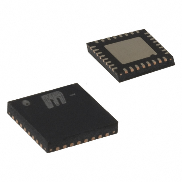
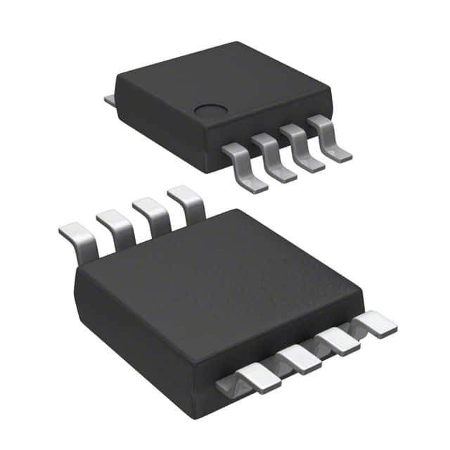
1.Package Type: Delay lines are typically housed in specific packages to provide mechanical protection and facilitate easy integration into electronic circuits. Common package types include DIP (Dual Inline Package), SOIC (Small Outline Integrated Circuit), QFN (Quad Flat No-Lead), and BGA (Ball Grid Array). The package type may vary based on the specific delay line technology and the manufacturer.
2.Size and Dimensions: The physical size of a delay line can vary depending on its complexity and the components used. Miniaturized delay lines are available for space-constrained applications, while larger delay lines may be used for higher power or specialized applications.
3.Pin Configuration: The number and arrangement of pins or terminals on a delay line depend on the specific implementation. Delay lines may have multiple input and output pins to accommodate the signal path and provide proper connectivity within the circuit. The pin configuration is often specified by industry standards or the manufacturer's design.
4.Input/Output Impedance: The input and output impedance of a delay line is an important consideration to ensure proper signal integrity and impedance matching. The impedance characteristics need to be compatible with the interfacing circuits to minimize reflections and signal distortions.
5.Frequency Range: Different delay lines have specific frequency ranges in which they operate effectively. The frequency range can be influenced by the internal components and the technology used. It is crucial to select a delay line that can handle the required frequency of the signals in the system.
6.Power Requirements: Delay lines may have specific power supply requirements, such as voltage levels and current consumption. These power requirements should be taken into account when integrating the delay line into the overall system design.
7.Environmental Considerations: Depending on the application, delay lines may need to meet certain environmental standards such as temperature range, humidity, shock, and vibration resistance. Some delay lines are designed for harsh operating conditions or are qualified for specific industries, such as automotive or aerospace.
These physical characteristics should be considered along with the electrical specifications and performance parameters of the delay line to ensure compatibility, reliability, and optimal performance within the intended application. It is recommended to consult the datasheets and specifications provided by the manufacturer for detailed information about the physical characteristics of a specific clock/timing delay line.
Electrical Characteristics of Clock/Timing - Delay Lines
Clock/timing delay lines have specific electrical characteristics that define their performance and compatibility with electronic systems. Here are some important electrical characteristics to consider:
1.Delay Range: The delay range indicates the minimum and maximum delay values that a delay line can provide. It is typically specified in units of time, such as nanoseconds (ns) or picoseconds (ps). The delay range determines the flexibility of the delay line in accommodating various timing requirements.
2.Delay Resolution: The delay resolution refers to the smallest increment of delay that can be achieved or adjusted in the delay line. It determines the granularity or precision of the delay adjustments. Higher delay resolution allows for finer timing adjustments.
3.Delay Accuracy: Delay accuracy refers to the deviation between the specified delay and the actual delay achieved by the delay line. It is typically expressed as a percentage or in terms of time (e.g., ±1 ns). Higher accuracy ensures that the desired timing relationships are maintained within the system.
4.Input/Output Voltage Levels: Delay lines have specific voltage level requirements for their input and output signals. It is important to ensure that the voltage levels of the delay line are compatible with the voltage levels of the interfacing circuits to ensure proper signal transfer and prevent signal distortions.
5.Signal Frequency Range: The signal frequency range indicates the range of frequencies that a delay line can handle effectively. It is important to choose a delay line that can accommodate the frequency range of the signals in the system without introducing significant signal degradation or distortion.
6.Signal Propagation Delay: The signal propagation delay is the time taken for a signal to propagate through the delay line. It is an inherent characteristic of the delay line and needs to be considered in the system design to account for the overall signal timing.
7.Signal Jitter: Jitter refers to the variation in the timing of a signal's edges or transitions. It can be caused by various factors such as noise, interference, or imperfections in the delay line. Lower jitter is desirable to ensure accurate and stable timing within the system.
8.Power Consumption: The power consumption of a delay line is an important consideration, especially in power-constrained applications. It is typically specified in terms of power supply voltage and current requirements.
9.Operating Temperature Range: The temperature range within which the delay line can operate reliably is specified as the operating temperature range. It is important to ensure that the delay line is suitable for the intended operating environment.
These electrical characteristics help determine the performance, compatibility, and reliability of the delay line within the electronic system. It is essential to consult the datasheets and specifications provided by the manufacturer for detailed information on the electrical characteristics of a specific clock/timing delay line.

