The Inductor Components is a basic circuit element in the circuit model in the discipline of circuit analysis, except for the resistance element R and the capacitance element C. In a linear circuit, the Inductor Components is represented by the inductance L. The "volt-ampere relationship" of components is a necessary constraint in linear circuit analysis in addition to Kirchhoff's laws.
An inductive element usually consists of a coil or coil consisting of windings and one or more magnetic cores such as iron cores. When current passes through the coil windings, the resulting magnetic field is stored in the core, which constitutes the basic principle of the inductive element.
Ⅰ. Working principle of inductor components
Inductive elements are based on electromagnetic induction, when current passes through an inductive element, it generates a magnetic field, which in turn interacts with the magnetic field generated by the current. Inductance is to wind the wire into a coil shape. When the current flows, a strong magnetic field will be formed at both ends of the coil (inductance). Due to the effect of electromagnetic induction, it will hinder the change of current. Therefore, the inductor presents a small resistance to DC (approximately a short circuit) and a high impedance to AC, and its resistance is related to the frequency of the AC signal passing through it. For the same inductive element, the higher the frequency of the alternating current, the greater the resistance.
1. Electromagnetic induction: The current in the inductive element will generate a magnetic field around it. This magnetic field is created by moving charges in an electric current. According to Faraday's law of electromagnetic induction, when the magnetic field changes, an induced electromotive force (voltage) is generated in the inductive element.
2. Mutual Inductance: The phenomenon that inductive components can also affect each other is called mutual inductance. When the magnetic fields of two inductive elements interact, an induced electromotive force is generated between them, causing a change in the potential difference. Mutual inductance is commonly found in multi-winding inductive components such as transformers.
3. Self-Inductance: When the current passes through the inductive element, the magnetic field generated will interact with the current passing through the element. This causes the potential difference across the inductive element to increase, thus resisting the change in current flow. This phenomenon is known as self-inductance, and the result is that the inductive element resists a sharp change in current, manifested as a self-induced voltage.
Ⅱ.Inductor component structure
Inductors can be made of a coiled core of electrically conductive material, typically copper wire, or the core can be removed or replaced with a ferromagnetic material. A core material with a higher permeability than air can more tightly confine the magnetic field around the inductive element, thus increasing the inductance.
The magnetic core is another important component in the inductor component. Magnetic cores are made of magnetic materials such as iron, nickel, ferrite, etc. Its role is to enhance the inductive inductance of the inductive element, because it concentrates and guides the magnetic field, thereby improving the interaction of the magnetic field with the winding.
The winding is the main part of the inductive component, usually made of insulated wire or coil. The wire is wound into one or more turns to form a tight coil structure. When current passes through the windings, a magnetic field is generated, which is the basis for the operation of inductive components.
Inductor component structure type:
1. Wind wire inductor
It is an inductive element without a magnetic core, and its winding is usually made of insulated wire and wound in air. Since there is no magnetic core to concentrate and guide the magnetic field, the inductive inductance of air-wire inductors is relatively low. Airwire inductors do not use iron cores or other magnetic materials, so there are no core losses.
Due to their low inductance, windwire inductors are often used in high frequency applications such as radio frequency (RF) circuits. Due to the lack of energy concentration of the magnetic core, the air-wire inductor may self-resonate at a certain frequency.
Wind wire inductors are commonly used in RF circuits for filtering, coupling, and impedance matching applications, where low inductive inductance and high frequency response are required. In high-frequency converters, wind wire inductors can be used to achieve current filtering and energy transmission.
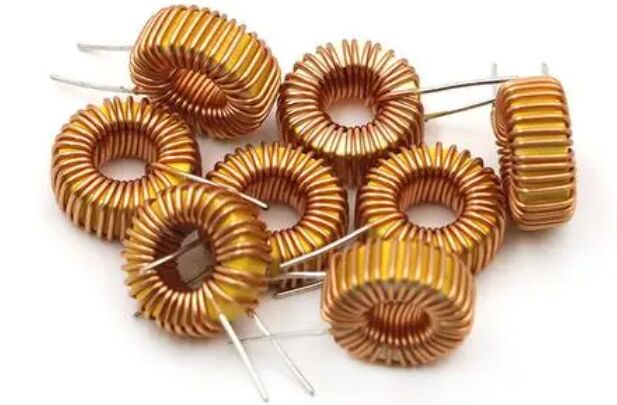
2. Iron core inductor
is an inductive component characterized by a magnetic core surrounding a winding, usually made of iron or other magnetic material. Iron core inductors usually have higher inductive inductance values due to the presence of the magnetic core. The magnetic core concentrates the magnetic field, thereby producing greater magnetic flux in the winding and enhancing the inductive inductance effect.
The magnetic core can reduce the leakage of magnetic field, allowing more magnetic field to be concentrated in the winding, improving the efficiency of the inductor element. The magnetic properties of the core mean that it can withstand relatively high currents without going into saturation easily. Iron core inductors are often used in low-frequency circuits, such as power supply filter circuits, resonant circuits, etc. In these applications, higher sensing inductance values are required to filter out low-frequency noise, stabilize the power supply, etc.
A transformer is a special type of iron-core inductor that utilizes two or more windings with a shared magnetic core to transform and transmit electrical energy. Iron core inductors can be used to stabilize power output, suppress sudden changes in current and voltage, and protect other electronic equipment from interference.
It is an electronic device based on the principle of electromagnetic induction and is used to convert AC voltage from one circuit to another. It usually consists of two or more windings (coils) and a shared magnetic core. Transformers are mainly used for transformation, transmission and distribution of electrical energy.
The working principle of a transformer is based on Faraday's law of electromagnetic induction. When an AC current passes through the main winding (primary) of a transformer, the resulting magnetic field causes a change in magnetic flux in the shared magnetic core. This changing magnetic flux in turn induces an electromotive force in the secondary winding (secondary), which produces an AC voltage on the secondary.
The transformation ratio of a transformer is the ratio of the primary voltage to the secondary voltage. The transformation ratio can be determined according to the ratio of winding turns. The transformation ratio determines the relationship between the input voltage and the output voltage of the transformer. Transformers can not only change voltage, but also transform current and power. Ideally, power is balanced in a transformer, that is, the input power equals the output power.
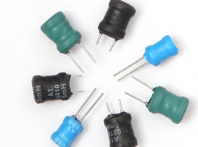
4.Multilayer winding inductor
It is an inductive component whose winding is stacked by multiple winding layers, and each winding layer is separated by insulating material. The design of multilayer winding inductors allows multiple winding layers to be stacked together to achieve high inductive inductance values in a limited space. The inductive inductance of each winding layer can be superimposed, enhancing the overall inductive effect.
The stacked design of multi-layer winding inductors can place multiple windings in a relatively small volume, thereby achieving a more compact size and suitable for applications with limited space. Multilayer winding inductors are commonly used in power modules to filter and stabilize power output, and to reduce current ripple in power lines.
In RF circuits, where smaller size highly inductive inductors are required, multilayer winding inductors can meet these needs, for example in filtering, coupling and matching circuits.
Ⅲ. The role of inductance components in the circuit
The function of the Inductor Components is to prevent the current from changing. It is different from the resistance to the current. The resistance to the current consumes the current, while the inductance is only relatively simple to prevent the current from becoming larger or smaller. It will not consume electric energy in the process of blocking the current, and It also temporarily stores electrical energy in the form of a magnetic field, and releases electrical energy when the current becomes smaller, so that the current will not change.
1. Inhibition of current changes: Inductive elements have an inhibitory effect on current changes, which is called the self-inductance of inductive elements. When the current changes, the Inductor Components generates a self-induced electromotive force to resist the change of the current. This can be used to stabilize the current in a circuit, preventing sharp increases or decreases in current.
2. Filters: Inductive components can be used to build various types of filters, such as low-pass filters, high-pass filters, band-pass filters, and band-stop filters. In filters, inductive elements are used together with capacitive elements in different arrangements to filter or pass signals within a specific frequency range. For example, a low-pass filter uses an inductive component to pass low-frequency signals while blocking high-frequency signals.
3. Energy storage and energy release: The inductive element can store electrical energy in the circuit, because when the current passes through the inductive element, a magnetic field will be generated in its winding, and this magnetic field stores electrical energy. When the current is reduced or interrupted, the magnetic field collapses, producing an induced electromotive force that allows the current to continue flowing, thereby releasing the stored electrical energy.
4. Oscillator: Inductance components can form an oscillation circuit together with capacitance components to generate periodic oscillation signals. In an oscillator, the interaction between the self-inductance of the inductive element and the charge and discharge of the capacitive element causes a periodic variation in the signal, resulting in oscillation.
5. Energy transmission: Inductive components can be used for wireless energy transmission, such as wireless charging technology. Through the principle of electromagnetic induction, the inductive element in the transmitter can generate a magnetic field, which induces the inductive element in the receiver to generate a current, thereby realizing energy transmission.
6. Coupling and transformation: Transformer is a special form of inductive element used to transfer electrical energy from one winding to another. The function of this transformer can be used for voltage conversion, current conversion and coupling signals. Transformers are widely used in power systems and communication systems.
7. Block DC current: Inductive components have a high blocking effect on DC current, because the self-inductance of the inductive component is only effective for changing currents. This allows inductive elements to create resistance in DC circuits.
Ⅳ. The difference between inductance and capacitance
1.Basic function
Inductor: An inductor is a component whose main function is to resist changes in current. When a current passes through an inductive element, the magnetic field generated resists sharp changes in the current, causing a potential difference when the current changes. An inductor stores energy in its internal magnetic field.
Capacitor: A capacitor is a component whose main function is to store and release electric charge. When a voltage is applied across a capacitive element, an electric field is created across it, allowing charge to be stored between the capacitive plates. Capacitors store energy in an electric field.
2. Structure
Inductor: refers to an electrical conductor that can carry current. The symbol is Henry, or Henry for short. The common unit of inductance is uh, mh.
Capacitor: It is two electrical conductors that are close to each other, and the insulating medium is filled in the middle to form a capacitor. The symbol of the inductor is farad, referred to as F, and the common capacitance unit is uF.
3. Symbol representation
Inductor: An inductive component is usually represented in a circuit diagram by a curved coil symbol.
Capacitor: Capacitive components are usually represented in circuit diagrams by two parallel flat plates with a gap between them to represent the electric field between the capacitive plates.
4. Function
Inductance: One of the main functions of an inductor is to resist sharp changes in current. When current passes through an inductive element, the magnetic field generated resists the change in current, causing a potential difference when the current changes. This property gives inductors an important role in current stabilization and filtering. An inductor can store energy in its internal magnetic field. When current flows through an inductor, the magnetic field stores electrical energy. This makes inductors useful in energy transfer and energy storage applications.
Capacitor: The main function of a capacitor is to store charge. When a voltage is applied across a capacitive element, an electric field is created across it, causing charge to be stored between the capacitive plates. This property enables capacitance to play a role in charge storage, energy transfer, and voltage stability. Capacitors can respond to voltage changes by charging and discharging. In AC circuits, capacitors can filter by responding to AC signals of different frequencies, passing or blocking signals of specific frequencies.
5.Principle
Inductance: The principle of inductance is based on the phenomenon of electromagnetic induction. When current passes through an inductive element, the magnetic field generated causes a change in magnetic flux. According to Faraday's law of electromagnetic induction, changing magnetic flux will generate an induced electromotive force in the inductive element, which resists changes in current. This self-induction effect causes the inductance to resist sharp changes in current.
Capacitance: The principle of capacitance is based on the electric field effect. A capacitor consists of two electrodes (usually metal plates) with an insulating material (dielectric) between them. When a voltage is applied to the two electrodes of a capacitor, an electric field is created between the two electrodes. This electric field causes electrons to flow from one electrode to the other, storing charge in the capacitor. The size of the capacitance depends on the dielectric properties, electrode area and electrode spacing.
6.Application
Inductor: Inductors can be used to suppress sharp changes in current. They can be used in AC circuits to smooth current waveforms and avoid sudden changes in current. Inductors can be used along with capacitors to build various types of filters such as low-pass filters, high-pass filters, and band-pass filters. They can filter by blocking or passing signals within a specific frequency range. Inductors play an important role in RF circuits for coupling, matching and filtering, as well as adjusting the frequency response of the circuit.
Capacitor: Capacitor is mainly used to store electric charge and thus energy in a circuit. Capacitors can be charged and discharged to store and release charge. Capacitors can be used together with inductors to build filters and coupling circuits. In power supply filtering, capacitors smooth voltage waveforms. In coupling, capacitors pass signals from one circuit to another. Capacitors can be used to build oscillation circuits to generate oscillation signals with stable frequencies, such as clock circuits and oscillators.
Ⅴ.Characteristics of inductance components
1. Induction: Inductance components work based on the principle of electromagnetic induction. When current passes through the winding, the magnetic field generated will cause changes in magnetic flux, thereby inducing an induced electromotive force in the winding. This inductive effect gives the inductor its ability to resist changes in current flow.
2. Inductance value: The inductance value of an inductance component is a measure of its resistance to changes in current.
3. Self-induction effect: The inductance component shows the self-induction effect, that is, when the current changes, a self-induction electromotive force will be generated in the inductance component to resist the sharp change of the current. This allows inductors to have applications in current stabilization and filtering.
4. Frequency response: The impedance of the inductor to AC current is proportional to the frequency. At low frequencies, the inductor has a low resistance to current flow, while at high frequencies, the inductor has a high resistance to current flow.
5. Inductive coupling: Multiple inductive components can be coupled together through a magnetic field to achieve signal transmission, isolation and transformation. This has applications in transformers, inductive couplers and filters.
6. Energy storage: Inductive components can store electrical energy in their windings by storing energy in the magnetic field of the windings. When current flows through an inductor, the magnetic field stores electrical energy.
Ⅵ. History of inductance components
1791-1867: Michael Faraday, one of the pioneers of electromagnetic induction, discovered in 1831 the induced electromotive force produced when an electric current passes through a wire. His research laid the foundations of the inductive element, especially the principles related to induction and magnetic fields.
1797-1878: Joseph Henry is a major figure in the field of electromagnetic induction. He conducted many experiments in the 1820s and 1830s to study the relationship between electric current and magnetic fields, contributing to the understanding and application of inductive components.
1831-1879: James Clerk Maxwell was one of the important contributors to electromagnetism. At the end of the 19th century, he proposed the famous Maxwell's equations, which describe the relationship between electric and magnetic fields. His work laid the foundations for the theory of electromagnetic induction and inductive elements.
1901-1977: Nobel's work had a profound impact on the development of inductive components. He invented the Nobel inductive coupler in the middle of the 20th century, an important inductive component used for coupling and voltage transformation in electronic circuits.
Ⅶ. How to achieve mutual inductance in inductance components
1. Mutual inductance refers to the phenomenon that two or more Inductor Componentss are coupled to each other through a magnetic field, causing the changing current in one Inductor Components to induce an electromotive force in the other Inductor Components.
Mutual inductance is a special case of electromagnetic induction. When the current changes, the magnetic field in one inductive element will affect another nearby inductive element, causing electromagnetic coupling between them.
2. Achieving mutual inductance usually requires placing multiple inductive components close enough so that their magnetic fields affect each other. In mutual inductance applications, there are usually two inductive components, referred to as the primary and secondary components. The changing current in the primary element generates a magnetic field, which affects the secondary element through space, thereby inducing an induced electromotive force in the secondary element.
3. The way to achieve mutual induction:
Physical Proximity: Placing the primary and secondary components in close enough proximity that their magnetic fields can couple to each other. Often this requires them to be physically close together, or even share the same magnetic circuit.
Transformer: Transformer is an important application of mutual inductance. In a transformer, there are two windings, one is the primary winding and the other is the secondary winding. When the current in the main winding changes, the generated magnetic field affects the secondary winding through the iron core, thereby inducing an electromotive force in the secondary winding to realize the transmission and conversion of electrical energy.
Shared magnetic circuit: In some applications, the primary and secondary components can achieve mutual inductance by sharing the same magnetic circuit. This means that their magnetic fields will produce changes in the common magnetic circuit, resulting in the phenomenon of mutual induction.
Ⅷ. Quality factor of inductive components
An ideal inductive element does not change its sensitivity due to the magnitude of the current flowing through the coil. However, in actual circumstances, the metal wires in the coil will cause the inductor element to have winding resistance. Since the winding resistance appears in the form of a resistance connected in series with the Inductor Components, it is also called a series resistance. Due to the existence of series resistance, the characteristics of the actual inductance component will be different from the ideal inductance. The quality factor can be used to express the ratio between the inductance and resistance.
The quality factor (Q) of an inductor is the ratio between its inductive reactance and resistance at a specific frequency. This ratio is used to measure the effectiveness of the inductor.
The quality factor Q of the inductor component can be obtained from the following equation, R is the internal reactance of the inductor component:
If ferromagnetic materials are used and other parts remain unchanged, the inductance will increase and therefore the quality factor will be improved. However, if the frequency increases, the inductance of ferromagnetic materials will decrease, that is, inductance is a variable of frequency. Under the same conditions, the greater the internal resistance, the smaller the quality factor. The quality factor can be regarded as one of the standards for measuring the quality of inductor components. The higher the quality factor usually means the better the quality of the inductor.