Ⅰ. Asynchronous counter
Ⅱ. Synchronous counter
Ⅲ. What is the synchronous counter?
Ⅳ. What is the difference between asynchronous and synchronous counters?
Ⅴ. What is the advantage of a synchronous counter?
Ⅵ. Why asynchronous counter is called the ripple counter?
The counter is mainly composed of flip-flops. According to the flip order of flip-flops, the counter can be divided into synchronous and asynchronous. In a synchronous counter, all flip-flops flip at the same time when the count pulse is input; while in an asynchronous counter, the flip-flops at all levels are not flipped simultaneously. If classified according to the increase or decrease of the number in the counter during the counting process, it can be divided into an addition counter, a subtraction counter and a reversible counter (also known as an up/down counter). The up-counter counts up with the continuous input of counting pulses; the down counter counts down with the continuous input of counting pulses; the up and down counters are called reversible counters.
Ⅰ. Asynchronous counter
The asynchronous counter also called ripple counter, is an asynchronous sequential circuit. Its main feature is that the clock pulse terminals CP of the internal flip-flops are not all connected together. Therefore, the flipping time of each flip-flop may come first, and its output may produce interference glitches, but its circuit structure is simple.
1.Pinout diagram and logic function
The figure below shows the pin arrangement diagram and logic function diagram of the asynchronous decimal counter 74290. It consists of three JK type triggers, one RS-type trigger, and several additional doors. R01 and R02 are asynchronous clear terminals: S91 and S92 are asynchronous set 9 terminals. The whole circuit can be seen as composed of two independent counters. Counter I is a one-bit binary counter composed of a flip-flop, the clock pulse terminal is CP0, and the status output terminal is Q0; Counter II is a five-ary asynchronous counter composed of three flip-flops, and its clock pulse terminal is CP1, and the status output terminal is Q1Q2Q3.
2.Asynchronous binary addition counter
The asynchronous binary counter is used to carry out bit by bit from low to high when counting up. Therefore, the flip-flops are not flipped synchronously. According to the binary addition counting rule, if the i-th bit is 1, it becomes 0 when 1 is added, and a carry signal is sent to the high bit to flip the high bit. If a T' flip-flop is used to form a counter circuit, only the Q terminal of the low flip-flop needs to be connected to the clock input terminal of the high flip-flop to realize the carry. When the low bit changes from 1 to 0, the falling edge of the Q terminal can be used as the high clock signal (if the T' flip-flop triggered by the falling edge is used), or the rising edge of the Q terminal can be used as the high clock signal (if the rising edge is used T' trigger).
3.Asynchronous decimal counter constructed with JK flip-flop
The asynchronous decimal addition counter is obtained on the basis of the 4-bit asynchronous binary addition counter, as shown in Figure. The main problem to be solved during the modification is how to make the 4-bit binary counter skip the 6 states of 1010-1111 during the counting process. Assuming that the selected flip-flops are all TTL when circuits J and K are floating, it is equivalent to a logic 1 level.
4.Asynchronous binary subtraction counter
According to the binary subtraction counting rule, if the low flip-flop is already 0, it should be flipped to 1 after another subtraction counting pulse is input, and a borrow signal is sent to the high bit to flip the high bit. If a T' flip-flop is used to form a counter circuit, then only the Q terminal of the low flip-flop needs to be connected to the clock input terminal of the high flip-flop to achieve carry. When the low bit changes from 0 to 1, the falling edge of the Q terminal can be used as the high clock signal (if the T' flip-flop triggered by the falling edge is used), or the rising edge of the Q terminal can be used as the high clock signal (if the rising edge is used T' trigger).
Ⅱ. Synchronous counter
Synchronous counter refers to the accumulated value of the measured value, which is characterized by greatly improving the working frequency of the counter, and corresponds to the asynchronous counter. For the synchronous counter, since the clock pulse acts on each flip-flop at the same time, the problem of the step-by-step delay of the flip-flop encountered by the asynchronous flip-flop is overcome, so the working frequency of the counter is greatly improved. However, if the number of synchronous counter stages increases, the load on the count pulse will increase.
1.Features
①The state of each flip-flop is updated simultaneously; ②The state of the flip-flop is determined by the current state of the previous stage and the next state of the subsequent stage; ③Compared with the asynchronous counter circuit structure, it needs the cooperation of the gate circuit, but the counting speed is faster than asynchronous counters; ④There are two types of methods of circuit carry: serial and parallel. The parallel carry method can further increase the counting speed.
2.Circuit configuration
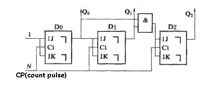
Asynchronous counters and synchronous counters are basically the same in principle, function, classification, etc. except for different circuit structures. Figure 1 is a three-bit binary addition counter with M=2 composed of three JK flip-flops. The count pulse N is added to the CP end of each flip-flop clock at the same time, and the flip-flop state update is performed simultaneously.
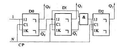
Figure 2 is a synchronous three-bit binary subtraction counter. The difference from Figure 1 is that each flip-flop leads from the Q terminal to the JK terminal of the next bit, and the non-Q enters the AND gate as the high-order JK terminal input.
What is the synchronous counter?
In synchronous counters, the counting sequence is controlled by means of a clock pulse and all the changes of the outputs of all flip-flops occur in synchronism. When the input pulse falls to the '0' level, the new values of the count are transmitted synchronously to the outputs of the flip-flops.
What is the difference between asynchronous and synchronous counters?
Synchronous counters have an internal clock, whereas asynchronous counters do not. As a result, all the flip-flops in a synchronous counter are driven simultaneously by a single, common clock pulse. This is the essential difference between synchronous and asynchronous counters.
What is the advantage of a synchronous counter?
The one advantage of synchronous counter over asynchronous counter is, it can operate on higher frequency than asynchronous counter as it does not have cumulative delay because of same clock is given to each flip flop.
Why asynchronous counter is called the ripple counter?
Asynchronous counters are sometimes called ripple counters because the data appears to “ripple” from the output of one flip-flop to the input of the next. They can be implemented using “divide-by-n” counter circuits.
标签:counter

