Ⅰ. Introduction to Relays
Ⅱ. Working principle of relay
Ⅲ. Basic steps of using the relay
Ⅳ. Precautions for using relays
Ⅴ.Common relay test
Ⅵ. Selection of relays
Ⅰ. Introduction to Relays
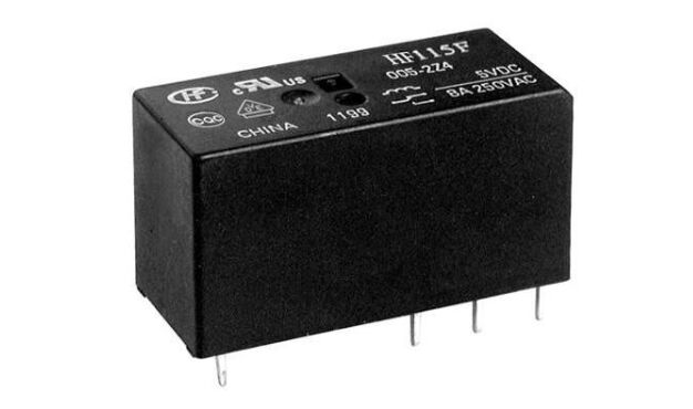
A relay is an electrical control device used to control the switching of one or more circuits in a circuit. It is an electromagnetic switch that can control the on-off of a large current through a small current, thereby realizing signal transmission and control in the electrical system. A relay usually consists of an electromagnetic coil, a core and contacts.
The relay, also known as the relay, is usually used in automatic control circuits. It is actually an "automatic switch" that uses a smaller current to control a larger current. Therefore, it plays the role of automatic adjustment, safety protection, and conversion circuit in the circuit.
A relay is an electrically controlled switching device that controls the operation of one or more switching elements by means of electromagnetic attraction. It is often used in occasions such as controlling small current to large current, isolating circuits, and realizing automatic control.
Ⅱ. Working principle of relay
The working principle of the relay is based on the phenomenon of electromagnetic induction. It uses the magnetic field generated by the electromagnetic coil to control the switching state of one or more contacts, so as to realize the control of one circuit to another circuit. A relay is an electrically operated switch that is remotely activated by an electromagnet that pulls on a set of contacts to make or break a circuit. Relays are commonly used to switch signals, wireless spot frequencies, high current circuits when using low current circuits, and loads such as resistive, motor, lamp, inductive and capacitive applications. Relays are useful when in-line switches or existing circuits are not capable of handling the required current.
Relays share the same subsystems and principles of operation, whether electromechanical or electronic, are relays used to switch signals or high-power loads. The relay converts the electrical input signal at the primary end into an intermediate non-electrical physical signal.
These devices also retransform non-electrical, physical signals to operate switching elements such as contacts that switch and conduct current. Relays utilize non-electrical signals between the primary and secondary sides to provide the necessary electrical isolation between the input and output circuits.
The relay supports the function of activating multiple circuits with a single output, which is helpful for cost saving, because the high current capacity switch costs more than the lower current version. The relay can also perform logic functions on certain inputs, such as latching the output on and off according to the instantaneous input. When the switch cannot accept high current or is operated by an electronic circuit, the relay can be operated by the switching circuit. The arc accompanied by contact bounce is one of the parameters to limit the inrush current. Care must be taken during the design and test phase of the application to avoid inrush current peaks exceeding the relay specifications.
Non-energized state: When the relay is in the non-energized state, no current passes through the electromagnetic coil, so no magnetic field is generated. In this case, the state of the contact is determined by its type, which can be closed or open.
Excitation state: When the current passes through the electromagnetic coil of the relay, the electromagnetic coil generates a magnetic field, which magnetizes the iron core. The magnetized core will attract the contacts, changing the state of the contacts.
Normally Open (NO) Contacts: In the energized state, the magnetic field of the solenoid coil attracts the contacts, causing them to open. This will cause the controlled circuit to close.
Normally Closed (NC) Contacts: In the energized state, the magnetic field of the solenoid coil attracts the contacts, causing them to close. This will cause a disconnection in the controlled circuit.
When the current passes through the electromagnetic coil, the relay is in the action state, and the state of the contact changes at this time. When the current stops passing through the electromagnetic coil, the relay is in the reset state and the contacts return to their initial state.
Ⅲ. Basic steps of using the relay
1. Determine the type and specification of the relay: firstly, it is necessary to determine the type and specification of the required relay according to the specific application requirements. The type of relay includes voltage type, contact type, number of contacts, etc., and the specifications include parameters such as excitation voltage, control current, load current, and load voltage.
2. Connect the relay: either socket or solder the relay to the board or an appropriate connector. Make sure the contacts and coil pins of the relay are properly connected to the circuit.
3. Provide power: The coil of the relay needs current to work. Current is supplied to the relay's coil by a suitable power source (usually low voltage).
4. Control signal: The relay usually has a control signal, usually a low level (such as 0V or ground) to activate the relay, or a high level (such as 5V or 12V) to close the relay.
5. Operate the relay: After the control signal is provided, the coil of the relay is activated to generate electromagnetic attraction force to make its contacts act. Contacts can be of the Normally Open (NO), Normally Closed (NC) or Changeover (COM) type, depending on the relay design.
6. Control external equipment: Through the contacts of the relay, the external equipment connected to the relay can be controlled. For example, relays can control high current loads, motors, lights, solenoid valves, etc.
7. Test and verification: After installing and debugging the relay, carry out the necessary test and verification to ensure that the relay works as expected and achieves the required control effect.
8. Closing and holding: After the control signal disappears, the coil of the relay loses the activation current, and the contacts return to the initial state. The contacts of the relay can remain in their switched position until the control signal is received again.
9. Maintenance: Regularly check the state of the relay, keep the contacts clean and in good contact, and replace aging or damaged relays in time to ensure the reliability and stability of the system.
Ⅳ. Precautions for using relays
1. Select the appropriate relay: According to the specific application requirements, select the appropriate relay type and specification, including parameters such as voltage type, contact type, contact capacity, excitation voltage and control current. Make sure the relay can withstand the required load current and voltage to avoid overload and damage; make sure the control signal matches the rated voltage and current of the relay. According to the current and voltage of the external equipment, select the appropriate relay model and rated parameters.
2. Power supply stability: The action and release of the relay have high requirements on power supply stability. When using relays, ensure that the power supply is stable, and avoid voltage fluctuations or frequent switching that cause relay malfunctions. Make sure the contacts of the relay are reliable enough to avoid contact arcing and failure.
3. Consideration of load capacity: Make sure that the load capacity of the relay is sufficient, and do not exceed the rated value in the relay specification. Excessive load may cause the contacts of the relay to burn out or make poor contact.
4. Safe maintenance: Regularly check the status of the relay to ensure that the contacts are clean and free from corrosion or wear. Damaged relays should be replaced in time to ensure reliable operation of the system. When using relays to control high voltage or high current, pay attention to safety measures to ensure circuit reliability and personnel safety.
5. Prevent vibration: The contacts in the relay are mechanical parts and are sensitive to vibration. When installing the relay, try to avoid strong mechanical vibration, so as not to affect the reliable contact of the contacts.
6. Avoid over-current and over-voltage: When using the relay, pay attention to prevent the occurrence of over-current and over-voltage, which may cause damage to the relay.
7. Clean the contacts: Regularly clean the contacts of the relay to ensure good contact. Contacts may be oxidized due to long-term use, affecting their electrical conductivity.
8. Temperature Note: The relay may be affected by the ambient temperature. In a high temperature environment, the performance of the relay may decrease, so choose a relay suitable for the ambient temperature or take heat dissipation measures.
Ⅴ.Common relay test
1. Static testing
Contact resistance test: Test the resistance value when the contact is closed. Make sure the contact resistance in the closed state is within specification to ensure good contact. Use the resistance file of the multimeter to measure the resistance of the normally closed contact and the moving point, and the resistance value should be 0.
Steps to measure relay contact resistance:
Before performing any tests, ensure that power to the relay has been disconnected to avoid electric shock and damage to the equipment. Then, remove the relay from the circuit so that a contact resistance test can be performed.
There are usually two sets of contacts in a relay, one normally closed (NC) and one normally open (NO). Identify the type of contact to be tested and record its location.
Select the multimeter to the resistance measurement gear, select an appropriate range, and ensure that the internal resistance of the multimeter will not affect the measurement results. Usually, select an appropriate gear to ensure that the measured resistance value is within the gear range.
Connect the multimeter's test probes to the contact terminals to be tested. Typically, one test probe is connected to one terminal of the contact and the other test probe is connected to the other terminal of the contact.
After connecting the test probes, read the resistance value displayed on the multimeter. This value is the resistance value of the contact. In the case of normally closed contacts, the measured value should approach zero when closed; in the case of normally open contacts, the measured value should approach infinity when open (open circuit).
If the relay has two sets of contacts (NC and NO), test both sets of contacts separately to ensure their resistance values are as expected.
After completing the contact resistance test, replace or repair as necessary and reinstall the relay in the circuit.
Contact test: The contact test is an important part of the relay test and is used to check the status and operation of the relay contacts.
Steps for contact testing:
Relays typically have two sets of contacts, one set of normally closed (NC) contacts and the other set of normally open (NO) contacts. Identify the type of contact to be tested and mark its location.
Connect the test probes of the multimeter to the contact terminals to be tested respectively. For normally closed contacts, one test probe is connected to one contact terminal and the other test probe is connected to the other contact terminal. For normally open contacts, the connection method is the same.
Analyze the state of the contacts based on the measurement results. If the contact resistance value deviates significantly from the normal range, it may mean that the contacts are poor or aging, and the relay may need to be replaced or maintained.
Measuring coil resistance: used to check the status and working conditions of the relay coil. A coil resistance test can be performed by using the resistance measurement function of a multimeter.
A relay usually has one or more coils, and the coil is the core component of the relay. Identify the coil location to be tested and record its identification.
Connect the test probes of the multimeter to each end of the coil. Typically, the ends of the coil are marked "+" and "-" and the test probes should be connected to the corresponding terminals.
After connecting the test probes, read the resistance value displayed on the multimeter. This value is the resistance value of the coil.
Analyze the state of the coil based on the measurement results. The coil resistance value should be close to the rated resistance value noted in the relay specification. If the coil resistance value deviates significantly from the rated value, it may indicate a damaged coil or other problem that may require replacement of the relay or maintenance.
2. Load test
Load testing is an important step in testing the load capacity and reliability of relays. In the load test, we connect the appropriate load to the contacts of the relay, simulating the load conditions carried by the relay in actual application, to ensure that the relay can control the load stably and work normally within the load range. Connect an appropriate load to the contacts of the relay and activate the relay. Make sure that the relay can control the load stably while observing whether the load current and voltage are within the relay specifications.
Steps for load testing:
According to the specifications of the relay and application requirements, determine the appropriate load parameters such as load current and load voltage.
Connect a suitable load (such as a lamp, motor, electrical equipment, etc.) to the contacts of the relay. Make sure that the connection to the load is secure.
Connect the relay's energizing circuit to activate the relay's solenoid. According to the excitation condition of the relay, provide the correct control signal.
Activates the solenoid of the relay, causing the contacts to operate. Observe whether the relay can control the load stably, and ensure that the load current and voltage are within the relay specifications.
Keep the relay active and continuously test its stability and reliability under load conditions. Observe the action state of the relay to ensure that it can work normally under load.
Analyze the behavior of the relay under load conditions based on the test results. If the relay behaves abnormally or does not operate stably under load conditions, it may be necessary to replace the relay or perform maintenance.
3. Motion test
Use the correct excitation voltage or current to activate the solenoid of the relay. Observe the operation of the contacts to ensure that the relay operates under the correct excitation conditions.
Confirm the stability of the contact action: the contact should act quickly after the excitation, and reset quickly after the excitation is released to ensure the stability and reliability of the action and release.
4. Measure the pull-in voltage and pull-in current
Measuring the pick-up voltage and pick-up current of the relay is an important test for the action characteristics of the relay, and these values are crucial for the normal operation of the relay. When testing pick-up voltage and pick-up current, the relay needs to be connected to the appropriate power and load circuits and measured with appropriate test equipment.
Steps to measure pickup voltage and pickup current:
Always disconnect power to the relay before testing to ensure safety. The relay is then removed from the circuit for pickup voltage and pickup testing.
Prepare an appropriate test circuit according to the specifications of the relay and the requirements of the application. Typically, the test circuit should include a suitable power supply and load. The load can be a load electrical appliance or a load resistor matched with the relay, so as to simulate the load condition that the relay picks up in the actual application.
Turn on the test power to activate the solenoid of the relay. Observe the action state of the relay, and record the measured values of the pick-up voltage and pick-up current.
Analyze the pull-in characteristics of the relay based on the measurement results. The pick-up voltage should be close to the rated pick-up voltage marked in the relay specification, and the pick-up current should be close to the rated pick-up current marked in the relay specification. If the pick-up voltage and pick-up current deviate significantly from ratings, it may indicate a problem with the relay and may require replacement or maintenance.
5. Measure the release voltage and release current
After the relay pulls in, gradually reduce the power supply voltage. When you hear the relay release sound again, record the voltage and current at this time. You can also try several times to obtain the average release voltage and release current. In general, the release voltage of the relay is about 10~50% of the pull-in voltage. If the release voltage is too high (less than 1/10 of the pull-in voltage), it cannot be used normally, which will threaten the stability of the circuit and work unreliably. When testing release voltage and release current, it is necessary to connect the relay to a suitable power supply and load circuit and use appropriate test equipment to measure it.
6. Temperature test
Test the working performance of the relay in high temperature and low temperature environment, and observe the action and release of the relay under different temperature conditions.
7. Cycle test
Perform multiple excitation and release operations to test the cycle life and stability of the relay to ensure that the relay can work stably for a long time.
Ⅵ. Selection of relays
1. According to load requirements: determine the type of load to be controlled (such as motors, light bulbs, solenoid valves, etc.) and the current and voltage requirements of the load. Select the rated current and voltage of the relay according to the load parameters to ensure that the relay can withstand the load requirements.
2. According to the excitation voltage: the excitation voltage of the relay is the minimum voltage value for the relay to operate. The excitation voltage is selected to be compatible with the control circuit to ensure that the relay can operate stably.
3. According to the contact type: The contact type of the relay usually has two types: normally closed (NC) and normally open (NO). According to the actual application needs, select the appropriate contact type.
4. According to environmental conditions: Contact type: The contact type of the relay usually has two types: normally closed (NC) and normally open (NO). According to the actual application needs, select the appropriate contact type.
5. According to package type: Relays have different package types, such as plug-in type, surface mount type, etc. Select the appropriate package type according to the actual installation method and space requirements.
6. According to the contact capacity: the contact capacity of the relay indicates the load current and voltage it can withstand. Make sure that the contact capacity of the relay is adequate for the maximum current and voltage of the required load.
标签:Relays

