Ⅰ. Logic - Parity Generators and Checkers
Ⅱ. Physical Characteristics of Logic - Parity Generators and Checkers
Ⅲ. Electrical Characteristics of Logic - Parity Generators and Checkers
Logic parity generators and checkers are essential components in digital systems used to detect errors in data transmission and storage. They provide a simple and effective means of error detection by adding a parity bit to the data and then verifying its correctness during reception. Let's explore the concept of logic parity generators and checkers in more detail:
Parity Generator:
A parity generator is a combinational logic circuit that generates a parity bit based on a set of data bits. The parity bit is an additional bit added to the data word, resulting in an extended word. The purpose of the parity bit is to provide error detection capabilities.
There are two common types of parity used in systems:
1.Even Parity: In even parity, the parity bit is chosen such that the total number of 1s (including the parity bit) in the data word is even. The parity bit is set to make the sum of 1s even. For example, if the data word has an odd number of 1s, the parity bit is set to 1 to make the total number of 1s even.
2.Odd Parity: In odd parity, the parity bit is chosen such that the total number of 1s (including the parity bit) in the data word is odd. The parity bit is set to make the sum of 1s odd. For example, if the data word has an even number of 1s, the parity bit is set to 1 to make the total number of 1s odd.
Parity Checker:
A parity checker is a combinational logic circuit that verifies the integrity of the received data by comparing it with the received parity bit. It checks whether any errors have occurred during data transmission or storage.
During reception, the received data word and the received parity bit are fed into the parity checker. The checker performs a parity calculation on the received data and compares it with the received parity bit.
For even parity checking, if the total number of 1s (including the received parity bit) is even, it indicates that no errors have occurred. If the total number of 1s is odd, it implies that an error has occurred.
For odd parity checking, if the total number of 1s (including the received parity bit) is odd, it indicates no errors. If the total number of 1s is even, it suggests an error.
If the parity checker detects an error, it generates an error signal to indicate the presence of an error condition. The error signal can be used to trigger error correction mechanisms or alert the system to the error.
Parity generators and checkers provide a basic form of error detection in digital systems. They are relatively simple and efficient methods for detecting single-bit errors. However, it's important to note that they do not correct errors, only detect them. For more robust error detection and correction, more advanced techniques like cyclic redundancy check (CRC) or Hamming codes are used.
Physical Characteristics of Logic - Parity Generators and Checkers
The physical characteristics of logic components, including parity generators and checkers, pertain to their physical attributes and properties. While the primary focus of parity generators and checkers lies in their functional behavior, certain physical characteristics can still be considered. Here are some relevant physical characteristics:
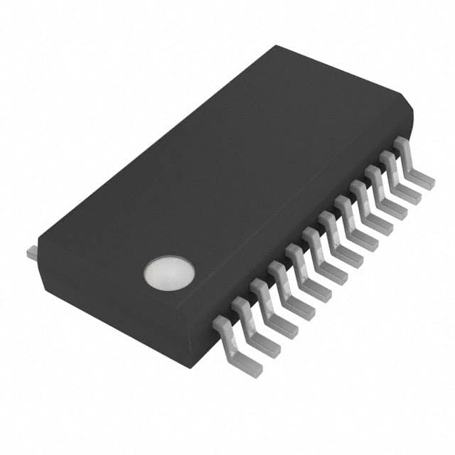
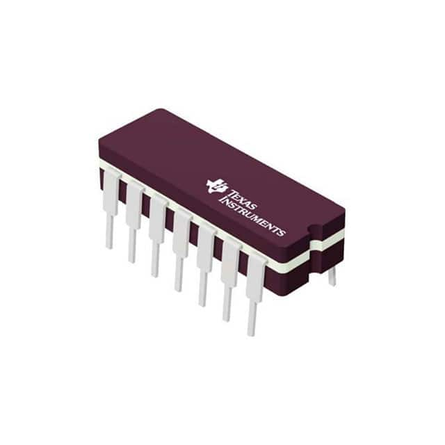
1.Integrated Circuit (IC) Packaging: Parity generators and checkers are typically implemented as integrated circuits (ICs). The physical packaging of these ICs can vary depending on the specific implementation and application. Common package types include Dual In-line Package (DIP), Small Outline Integrated Circuit (SOIC), Ball Grid Array (BGA), and Quad Flat Package (QFP). The packaging influences the size, pin configuration, and thermal properties of the IC.
2.Pin Configuration: Parity generators and checkers have specific pin configurations that define the arrangement and assignment of their input and output pins. The pin configuration determines how the IC is physically connected and interfaced with other components in a circuit or system. The number and arrangement of pins may vary based on the specific implementation and packaging of the IC.
3.Power Supply Requirements: Like any other digital logic component, parity generators and checkers have specific power supply requirements. These requirements typically include operating voltage levels and current consumption. The power supply requirements need to be met for the proper functioning of the IC, and the power source must provide the necessary voltage and current capabilities.
4.Thermal Considerations: Parity generators and checkers generate heat during operation, which must be dissipated to ensure the IC's reliability and longevity. The physical characteristics of these components, such as package type, thermal conductivity, and heat dissipation mechanisms, play a role in managing and regulating the temperature of the IC. Adequate heat sinking and thermal management techniques may be employed to prevent excessive temperature rise.
5.Electrostatic Discharge (ESD) Protection: Electronic components, including parity generators and checkers, are susceptible to damage from electrostatic discharge (ESD). Proper ESD protection mechanisms should be implemented in the physical design of the IC to safeguard against ESD events during handling and operation. These protections may include ESD diodes, shielding, and appropriate grounding techniques.
While the primary focus of parity generators and checkers lies in their logical functionality and error detection capabilities, considering the physical characteristics is important for proper integration, compatibility, and reliability in a digital system. Ensuring proper packaging, pin configuration, power supply, thermal management, and ESD protection contribute to the overall performance and longevity of these logic components.
Electrical Characteristics of Logic - Parity Generators and Checkers
The electrical characteristics of logic components, including parity generators and checkers, are crucial to their proper operation and integration within a digital system. These characteristics determine how the components interact with other circuitry and ensure reliable data transmission and error detection. Here are some key electrical characteristics of parity generators and checkers:
1.Operating Voltage: Parity generators and checkers have specified operating voltage ranges within which they function correctly. The operating voltage is the voltage level required for the components to operate reliably and provide accurate logic levels for inputs and outputs. It is important to supply the components with the appropriate voltage level to ensure proper functionality and prevent damage.
2.Logic Levels: Logic components, including parity generators and checkers, operate based on specific voltage levels that represent different logic states. The logic levels determine how the components interpret and process the input and output signals. Common logic levels include high or "1" (typically represented by a voltage close to the supply voltage) and low or "0" (typically represented by a voltage close to ground). The voltage thresholds for determining these logic levels depend on the specific technology and standard being used.
3.Input and Output Characteristics: Parity generators and checkers have defined input and output characteristics that specify the voltage levels and current requirements for their inputs and outputs. These characteristics include parameters such as input voltage levels, input impedance, output voltage levels, output current capabilities, and output impedance. Adhering to these characteristics ensures proper interfacing and signal integrity between the components and other circuitry in the system.
4.Propagation Delay: Propagation delay refers to the time it takes for a signal to propagate through a logic component, including parity generators and checkers. It is the delay between the input signal transition and the corresponding output signal transition. Propagation delay depends on the internal circuitry and design of the component and can vary based on factors such as load capacitance, operating voltage, and temperature. Minimizing propagation delay is important for maintaining accurate timing and signal synchronization.
5.Power Consumption: Parity generators and checkers consume power during their operation. The power consumption is influenced by factors such as operating voltage, switching frequency, and the complexity of the internal circuitry. Understanding the power consumption characteristics is important for system-level power budgeting and ensuring that the power supply can meet the components' requirements.
6.Noise Immunity: Parity generators and checkers are designed to be immune to noise and interference to ensure reliable operation. They incorporate techniques such as noise filtering, signal conditioning, and noise margin design to tolerate variations in voltage levels and minimize the impact of electrical noise on signal integrity. Noise immunity is particularly important in environments with high noise levels or in systems operating at high speeds.
7.ESD Protection: Electrostatic discharge (ESD) protection is crucial for protecting logic components, including parity generators and checkers, from damage due to electrostatic discharge events. ESD protection mechanisms, such as ESD diodes, help prevent the buildup and discharge of static charges that can cause permanent damage to the components. Proper ESD protection is vital for maintaining the reliability and lifespan of the components.
Understanding and considering the electrical characteristics of parity generators and checkers is essential for their successful integration and operation within a digital system. Adhering to specified voltage levels, input/output characteristics, propagation delay, power consumption, noise immunity, and ESD protection guidelines ensures reliable performance, compatibility, and system-level integrity.

