Ⅰ. Logic - Gates and Inverters - Multi-Function, Conf
Ⅱ. Physical Characteristics of Logic - Gates and Inverters - Multi-Function, Conf
Ⅲ. Electrical Characteristics of Logic - Gates and Inverters - Multi-Function, Conf
Logic - Gates and Inverters - Multi-Function, Conf
Logic Gates:
Logic gates are fundamental building blocks in digital circuits. They perform basic logical operations on one or more binary inputs and produce a single binary output. The output is determined based on the logical function applied to the input signals.
There are several types of logic gates, including:
1.AND Gate: The AND gate produces a high (1) output only when all of its inputs are high. Otherwise, the output is low (0).
2.OR Gate: The OR gate produces a high output if any of its inputs are high. It only gives a low output when all inputs are low.
3.NOT Gate (Inverter): The NOT gate, also known as an inverter, has a single input and produces the opposite output. For example, if the input is high, the output will be low, and vice versa.
4.NAND Gate: The NAND gate is a combination of an AND gate followed by a NOT gate. It produces a low output only when all inputs are high; otherwise, it gives a high output.
5.NOR Gate: The NOR gate is a combination of an OR gate followed by a NOT gate. It produces a high output only when all inputs are low; otherwise, it gives a low output.
6.XOR Gate: The XOR (exclusive OR) gate produces a high output if the number of high inputs is odd; otherwise, it gives a low output.
7.XNOR Gate: The XNOR (exclusive NOR) gate produces a high output if the number of high inputs is even; otherwise, it gives a low output.
Multi-Function Logic Gates:
Multi-function logic gates are gates that can implement multiple logic functions within a single gate. They provide flexibility and reduce the number of physical gates required in a circuit. For example, a single gate can perform the functions of an AND, OR, and NOT gate.
Common examples of multi-function logic gates include the Universal NAND gate and the Universal NOR gate. These gates can be configured to implement any logic function by properly connecting their inputs.
Configuration:
The configuration of logic gates refers to how the inputs and outputs are connected to form a desired logic function. By changing the arrangement of inputs and outputs, different logical operations can be achieved.
For example, if you connect the output of an AND gate to the input of a NOT gate, you create an AND-NOT configuration, which is equivalent to a NAND gate. Similarly, connecting the output of an OR gate to a NOT gate creates an OR-NOT configuration, equivalent to a NOR gate.
Configuring logic gates allows you to create more complex logic functions and implement specific requirements in digital circuits.
Physical Characteristics of Logic - Gates and Inverters - Multi-Function, Conf
The physical characteristics of logic gates, inverters, and multi-function gates can vary depending on the specific technology used for implementation. Here are some general aspects to consider:
1.Integrated Circuits (ICs): Logic gates, inverters, and multi-function gates are commonly implemented using integrated circuit technology. These circuits are typically manufactured on a silicon substrate using processes like Complementary Metal-Oxide-Semiconductor (CMOS) or Transistor-Transistor Logic (TTL).
2.Transistors: The basic building blocks of logic gates and inverters are transistors. CMOS technology employs both NMOS (n-channel metal-oxide-semiconductor) and PMOS (p-channel metal-oxide-semiconductor) transistors, while TTL technology mainly uses bipolar junction transistors (BJTs).
3.Input/Output Pins: Logic gates, inverters, and multi-function gates usually have multiple input pins and a single output pin. The number of inputs varies depending on the gate's functionality, such as two inputs for an AND gate or three inputs for an XOR gate.
4.Power Supply: Logic gates require a power supply to operate. CMOS gates typically operate with a power supply voltage of 3.3V or 5V, while TTL gates usually work with a power supply voltage of 5V.
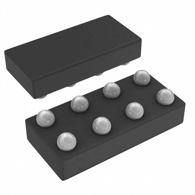
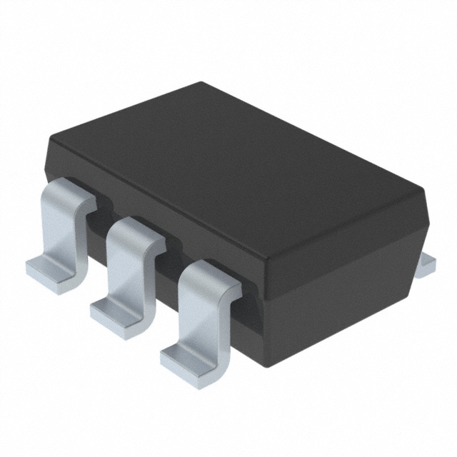
5.Package Types: Logic gates and inverters are packaged in various formats, such as Dual In-line Package (DIP), Small Outline Integrated Circuit (SOIC), or Ball Grid Array (BGA). The package type defines the physical dimensions, pin layout, and mounting method for the integrated circuit.
6.Speed and Delay: Logic gates have a propagation delay, which is the time it takes for a change in the input to propagate to the output. Different gate technologies have different speed characteristics, with CMOS generally providing faster operation and lower power consumption compared to TTL.
7.Noise Immunity: CMOS gates offer better noise immunity because of their differential design, which reduces susceptibility to external electrical noise. TTL gates, on the other hand, may be more sensitive to noise interference.
8.Fan-Out: Fan-out refers to the number of gates that can be driven by the output of a particular gate without causing signal degradation. The fan-out capability depends on factors like the output current capacity of the gate and the technology used.
9.Configurability: Multi-function gates offer the advantage of configurability, allowing them to implement different logic functions within a single gate. This reduces the number of physical gates required in a circuit and simplifies design complexity.
Electrical Characteristics of Logic - Gates and Inverters - Multi-Function, Conf
The electrical characteristics of logic gates, inverters, and multi-function gates are essential to consider when designing and working with digital circuits. Here are some key electrical characteristics:
1.Operating Voltage (VCC): Logic gates have a specified operating voltage range within which they function correctly. Common voltage levels include 3.3V and 5V for CMOS technology and 5V for TTL technology. It is important to ensure that the power supply voltage matches the requirements of the specific gates being used.
2.Input Voltage Levels: Logic gates have defined input voltage levels to interpret logic states. For example, in CMOS technology, a high logic level (logic 1) typically corresponds to a voltage close to VCC, while a low logic level (logic 0) corresponds to a voltage close to ground (0V). TTL gates have specific voltage thresholds for determining logic levels.
3.Output Voltage Levels: Logic gates produce specific voltage levels at their outputs for different logic states. In CMOS technology, a high logic level output (logic 1) is close to VCC, while a low logic level output (logic 0) is close to ground. TTL gates typically have a higher voltage for a logic 1 output and a lower voltage for a logic 0 output.
4.Output Current (Sink/Source): The output current capability of logic gates refers to their ability to either sink current (provide a low output) or source current (provide a high output). This characteristic is important when driving other gates or devices connected to the output.
5.Power Consumption: Logic gates consume power from the power supply during operation. CMOS gates have very low static power consumption but consume power when switching states. TTL gates typically consume more power compared to CMOS gates.
6.Propagation Delay: Propagation delay refers to the time it takes for a signal to propagate through a gate from the input to the output. It is an important parameter to consider for timing-sensitive applications. CMOS gates generally have shorter propagation delays compared to TTL gates.
7.Noise Margin: Noise margin defines the level of noise immunity or tolerance of a gate's input signals. It represents the difference between the minimum acceptable voltage for a logic 1 and the maximum acceptable voltage for a logic 0. A larger noise margin provides better immunity to noise interference.
8.Fan-Out: Fan-out is the maximum number of inputs that a gate's output can drive while maintaining proper logic levels. It depends on the output current capability of the gate and the input capacitance of the following gates.
9.Temperature Range: Logic gates have specified operating temperature ranges within which they can function reliably. It is important to ensure that the operating temperature does not exceed the specified limits to avoid performance issues or damage.
These electrical characteristics can vary depending on the specific technology, family, and manufacturer of the logic gates and inverters.

