FIFO (First-In, First-Out) is a type of memory that operates based on the principle of data being written in the order it arrives and read out in the same order. It is commonly used in digital systems to buffer and manage data transfers between two asynchronous processes.
Ⅰ. Key Features of FIFO Memory
Ⅱ. Applications of FIFO Memory
Ⅲ. Physical Characteristics of Logic - FIFOs Memory
Ⅳ. Electrical Characteristics of Logic - FIFOs Memory
Key Features of FIFO Memory:
1.Structure: A FIFO memory consists of a series of storage locations or registers organized in a sequential manner. The storage locations are connected in a queue-like structure.
2.Data Flow: FIFO memory operates on a first-in, first-out basis. When data is written into the FIFO, it is stored at the write end, and when data is read from the FIFO, it is retrieved from the read end. This ensures that the oldest data in the FIFO is read out first.
3.Write and Read Pointers: FIFO memory utilizes two pointers, namely the write pointer (also known as the input pointer) and the read pointer (also known as the output pointer). These pointers keep track of the write and read positions in the FIFO.
4.Write Operation: During a write operation, data is written into the FIFO at the write pointer's position, and the write pointer is advanced to the next location. This allows new data to enter the FIFO.
5.Read Operation: During a read operation, data is read from the FIFO at the read pointer's position, and the read pointer is advanced to the next location. This allows data to be retrieved from the FIFO in the order it was written.
6.Empty and Full Conditions: A FIFO memory can be in different states based on the number of data elements present. When the FIFO is empty, the write and read pointers are at the same position, indicating that no data is available for reading. When the FIFO is full, the write pointer has caught up with the read pointer, indicating that no more data can be written until some data is read out.
7.Data Width and Depth: FIFO memories have a specific data width, which refers to the number of bits in each data element. The depth of the FIFO represents the total number of storage locations or the maximum number of data elements that the FIFO can hold.
8.Synchronous and Asynchronous FIFOs: FIFO memories can be implemented using synchronous or asynchronous designs. Synchronous FIFOs are controlled by a clock signal and operate in synchronization with the clock. Asynchronous FIFOs, on the other hand, operate independently of a clock and are designed to handle data transfers between different clock domains.
Applications of FIFO Memory:
FIFO memories find applications in various scenarios where data buffering, synchronization, or flow control is required. Some common applications include:
1.Data Transfer: FIFOs are used to buffer data between different components or subsystems that operate at different speeds or have different data arrival rates.
2.Data Synchronization: FIFOs help synchronize data transfers between asynchronous processes or devices by temporarily storing data until it can be processed or transmitted at the appropriate time.
3.Data Flow Control: FIFOs are employed to control the flow of data in systems with varying data rates, ensuring that data is processed or transmitted in a controlled manner.
4.Real-Time Systems: FIFOs play a crucial role in real-time systems where the timing and order of data processing are critical.
5.Communication Systems: FIFOs are used in communication systems to buffer and manage data transfers between different parts of the system, such as between a transmitter and a receiver.
FIFO memories provide a means to manage data transfers and ensure proper synchronization between different components or processes in digital systems. They are a vital component in the design and implementation of various digital circuits and systems.
Physical Characteristics of Logic - FIFOs Memory
The physical characteristics of FIFO (First-In, First-Out) memory refer to the physical properties and specifications of the memory module. These characteristics include the size, packaging, pin configuration, and other physical aspects. Here are some key physical characteristics of FIFO memory:
1.Operating Temperature Range: FIFO memory modules have specified operating temperature ranges within which they can function reliably. It is important to ensure that the operating temperature does not exceed the specified limits to avoid performance issues or damage to the module.
2.Mounting Method: FIFO memory modules are mounted onto printed circuit boards (PCBs) using various methods such as through-hole mounting or surface-mount technology (SMT). The mounting method determines how the module is physically attached to the PCB.
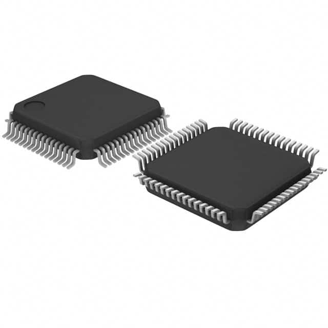
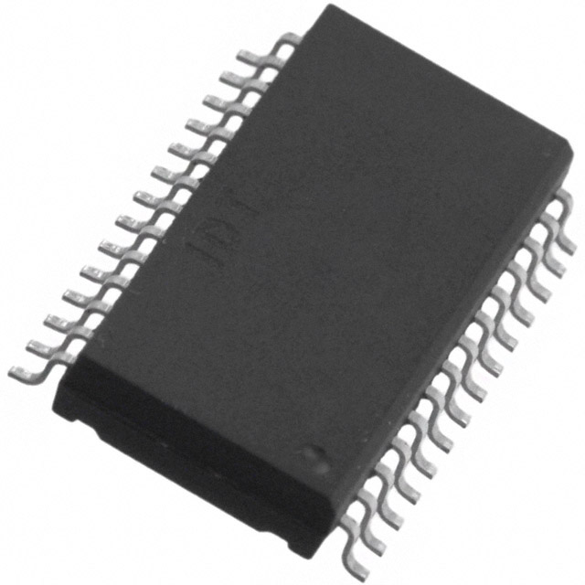
3.Package Type: FIFO memory modules come in various package types, such as Dual In-line Package (DIP), Small Outline Integrated Circuit (SOIC), Thin Small Outline Package (TSOP), and Ball Grid Array (BGA). The package type determines the physical dimensions, pin arrangement, and mounting method of the memory module.
4.Package Size: The physical dimensions of the FIFO memory module are specified by its package size. The package size is typically measured in terms of length, width, and height, and it determines the overall physical footprint of the module.
5.Pin Configuration: FIFO memory modules have a specific pin configuration that defines the connection points for power supply, input data, output data, control signals, and other relevant signals. The pin configuration is typically specified in the datasheet of the memory module.
6.Pin Count: The pin count refers to the total number of pins on the FIFO memory module. The pin count can vary depending on the specific module and package type. It includes pins for power supply, data input, data output, control signals, and other necessary connections.
7.Voltage Requirements: FIFO memory modules have specific voltage requirements for proper operation. These voltage requirements include the supply voltage (VCC) and ground reference (GND). It is important to ensure that the power supply voltage matches the specified voltage range for the module.
8.Capacity: The capacity of a FIFO memory module is the maximum number of data elements it can store. It is typically specified in terms of the total number of words, bytes, or bits that can be accommodated by the module.
9.Data Width: The data width of a FIFO memory module refers to the number of bits in each data element that can be stored in the memory. It is an important specification to consider when determining the module's capacity and compatibility with the data width requirements of the system.
10.Packaging Material: The material used for the packaging of FIFO memory modules can vary. Common packaging materials include plastic, ceramic, or metal. The choice of packaging material can influence factors such as durability, thermal characteristics, and cost.
These physical characteristics may vary depending on the specific manufacturer, product line, and module specifications.
Electrical Characteristics of Logic - FIFOs Memory
The electrical characteristics of FIFO (First-In, First-Out) memory refer to the electrical properties and specifications that govern its operation and interface with other components in a digital system. These characteristics include voltage levels, timing parameters, signal levels, and other electrical aspects. Here are some key electrical characteristics of FIFO memory:
1.I/O Interface Standards: FIFO memory modules often follow specific interface standards such as TTL (Transistor-Transistor Logic), CMOS (Complementary Metal-Oxide-Semiconductor), LVCMOS (Low-Voltage CMOS), or LVDS (Low-Voltage Differential Signaling). These standards define the electrical characteristics of the interface signals, including voltage levels, signaling methods, and impedance requirements.
2.Power Consumption: FIFO memory modules consume power during operation. The power consumption is typically specified in terms of supply current or power dissipation. Understanding the power requirements of the module is important for proper power supply design and overall system power management.
3.Clock Frequency: FIFO memory modules often utilize clock signals to control the timing of data transfers and operations. They have a specified clock frequency range, indicating the maximum frequency at which the module can operate reliably. Operating the module beyond the specified clock frequency range may result in data errors or malfunctions.
4.ESD Protection: FIFO memory modules may incorporate built-in Electrostatic Discharge (ESD) protection circuitry to safeguard against electrostatic discharge events that could damage the module. The ESD protection level is typically specified to ensure proper handling and usage of the module.
5.Operating Voltage: FIFO memory modules have a specified operating voltage range within which they function correctly. It is crucial to provide the required voltage level (typically specified as VCC) to ensure proper operation of the module.
6.Input and Output Voltage Levels: FIFO memory modules have defined voltage levels for their input and output signals. These voltage levels are typically specified as high-level voltage (VH) and low-level voltage (VL). The module's inputs and outputs should adhere to these voltage levels to ensure reliable data transfer and compatibility with other system components.
7.Input and Output Current Levels: FIFO memory modules have maximum input and output current ratings that should not be exceeded to prevent damage to the module or the driving circuitry. It is important to ensure that the input and output circuitry can handle the specified current levels.
8.Input and Output Timing: FIFO memory modules have specific timing requirements for their input and output signals. These timing parameters include setup time, hold time, data access time, and clock-to-output delay. It is crucial to meet these timing specifications to ensure proper data transfer and synchronization between the module and other system components.
9.Noise Immunity: FIFO memory modules may have specified noise immunity levels to ensure reliable operation in the presence of electrical noise or disturbances. Noise immunity refers to the module's ability to tolerate and reject unwanted electrical signals or fluctuations.
These electrical characteristics may vary depending on the specific manufacturer, product line, and module specifications.

