Ⅰ. Logic - Counters, Dividers
Ⅱ. Physical Characteristics of Logic - Counters, Dividers
Ⅲ. Electrical Characteristics of Logic - Counters, Dividers
Counters and dividers are fundamental components of digital circuits that perform counting and frequency division operations. They play a crucial role in various applications where precise timing, event counting, or frequency scaling is required. Let's delve into their introduction:
1.Counters:
Counters are sequential logic circuits that generate a sequence of binary numbers in response to clock pulses. They can be used to count events, track the number of occurrences of an event, or generate timing signals. Counters consist of a series of flip-flops connected in a specific configuration to form a register.
The basic operation of a counter involves the following steps:
(1.)The counter is initialized to a specific starting value.
(2.)On each clock pulse, the counter increments its value by one.
(3.)When the maximum count value is reached, the counter may either wrap around and start from the initial value again (modulus-N counter), or it can be designed to stop counting or trigger a specific action (such as generating an output signal).
Counters can be synchronous or asynchronous:
(1.)Synchronous Counters: In synchronous counters, all flip-flops are driven by the same clock signal, ensuring that they change their states simultaneously. This eliminates the issues of ripple propagation delay and ensures accurate counting.
(2.)Asynchronous Counters: Asynchronous counters, also known as ripple counters, have flip-flops connected in a cascaded manner, where the output of one flip-flop serves as the clock input for the next flip-flop. As the name suggests, the state changes ripple through the flip-flops sequentially, introducing a delay in the count progression. Asynchronous counters are simpler to implement but can suffer from glitches and propagation delays.
Counters can be designed to count in different sequences, such as up counters (incrementing the count), down counters (decrementing the count), or up-down counters (counting up and down based on control inputs). They are widely used in applications such as frequency synthesis, timekeeping, event counting, and digital signal processing.
2.Dividers:
Dividers, also known as frequency dividers or frequency counters, are circuits used to divide an input clock signal by a specific integer value. The output of the divider produces a signal with a lower frequency compared to the input signal. Dividers are commonly used for frequency scaling, generating clock signals with different timing requirements, or dividing down high-frequency signals for processing by slower circuits.
Dividers can be implemented using counters or dedicated divider circuits. They have a divide-by-N configuration, where N represents the division factor. For example, a divide-by-2 divider halves the input frequency, while a divide-by-8 divider divides the input frequency by 8.
Dividers can operate synchronously or asynchronously, depending on the specific implementation and requirements of the digital circuit.
Counters and dividers are fundamental components in digital systems, enabling precise timing control, event counting, and frequency scaling. They are widely used in applications such as digital clocks, microcontrollers, communication systems, frequency synthesizers, and many other digital devices.
Physical Characteristics of Logic - Counters, Dividers
The physical characteristics of logic counters and dividers can vary depending on their specific implementation and the technology used. However, there are some common physical aspects to consider:
1.Integrated Circuits (ICs): Counters and dividers are often implemented as integrated circuits (ICs) or digital chips. These ICs contain the necessary logic circuitry, flip-flops, and other components required for counting or dividing signals. ICs provide compactness, ease of manufacturing, and improved performance due to their integration.
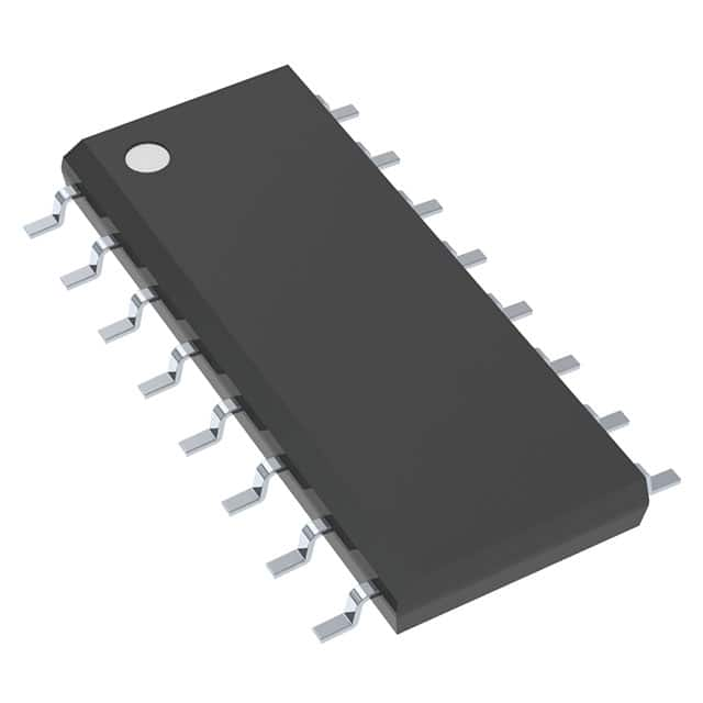
2.Package Types: Logic counters and dividers, when implemented as ICs, are typically packaged in various forms to protect the underlying silicon and provide electrical connections. Common package types include Dual Inline Package (DIP), Small Outline Integrated Circuit (SOIC), Quad Flat Package (QFP), Ball Grid Array (BGA), and more. The choice of package depends on factors such as pin count, size, thermal considerations, and manufacturing requirements.
3.Technology: Counters and dividers can be implemented using various technologies, such as Transistor-Transistor Logic (TTL), Complementary Metal-Oxide-Semiconductor (CMOS), or Emitter-Coupled Logic (ECL). Each technology has its own advantages and trade-offs in terms of speed, power consumption, voltage levels, and noise immunity.
4.Power Consumption: Power consumption is an important consideration in digital circuits, including counters and dividers. It refers to the amount of electrical power consumed by the component during operation. Minimizing power consumption is important for reducing heat dissipation and optimizing energy efficiency.
5.Voltage and Current Ratings: Counters and dividers operate within specified voltage and current ranges. The voltage rating indicates the maximum voltage that the component can handle, while the current rating specifies the maximum current it can safely carry. These ratings are important considerations for circuit design and ensuring proper operation.
6.Pin Configuration: The physical appearance of logic counters and dividers is determined by the pin configuration of the integrated circuit. The pins on the package provide the electrical connections required for power supply, clock input, control inputs, and output signals. The pin count and arrangement can vary depending on the specific counter or divider design.
7.Speed and Frequency Range: Counters and dividers have associated speed characteristics, often measured in terms of maximum operating frequency. This represents the maximum clock frequency at which the counter or divider can reliably operate. The frequency range indicates the input and output signal frequencies that the component can handle.
These physical characteristics of logic counters and dividers are influenced by factors such as the specific manufacturer, technology, design considerations, and intended application. Engineers consider these factors while selecting and integrating counters and dividers into digital circuits, ensuring compatibility, performance, and reliability.
Electrical Characteristics of Logic - Counters, Dividers
The electrical characteristics of logic counters and dividers are important considerations for their proper operation and integration within digital circuits.
Here are some key electrical characteristics to consider:
1.Supply Voltage (VCC): The supply voltage, often denoted as VCC, represents the voltage level required to power the counter or divider circuit. It determines the operating voltage range within which the component functions correctly. The datasheet or specifications provided by the manufacturer will indicate the recommended supply voltage range.
2.Input and Output Currents: The input current (Iin) and output current (Iout) characteristics are important for proper signal integrity and driving capabilities. Input currents determine the amount of current required to maintain proper logic levels at the input pins, while output currents represent the maximum current that can be sourced or sunk at the output pins.
3.Logic Levels: Logic counters and dividers operate with specific voltage levels to represent binary states. Common logic families include TTL (Transistor-Transistor Logic), CMOS (Complementary Metal-Oxide-Semiconductor), and LVCMOS (Low-Voltage CMOS). The logic levels, such as high (H) and low (L) voltage thresholds, define the voltage ranges at which the inputs and outputs are considered as logic high or logic low.
4.Noise Immunity: Counters and dividers should have good noise immunity to ensure reliable operation. Noise immunity refers to the ability of the component to reject or tolerate electrical noise present in the environment. It is typically specified in terms of noise margin, which is the difference between the minimum acceptable logic high voltage level and the maximum acceptable logic low voltage level.
5.Power Consumption: Power consumption is a critical consideration in digital circuits, including counters and dividers. It refers to the amount of electrical power consumed by the component during operation. Power consumption is typically measured in terms of power supply current (ICC) and depends on factors such as the number of flip-flops, clock frequency, and technology used. Minimizing power consumption is important for reducing heat dissipation and optimizing energy efficiency.
6.Fan-Out: Fan-out refers to the maximum number of inputs or outputs that a counter or divider can drive without significant degradation of signal quality. It indicates the capability of the component to deliver or receive signals to/from multiple destinations without causing voltage level distortions or excessive delays.
7.Propagation Delay: Propagation delay refers to the time it takes for a signal to propagate through the counter or divider circuit from input to output. It is an important parameter that affects the overall performance and timing of the digital circuit. Shorter propagation delays are desirable for high-speed applications to minimize signal latency and ensure accurate timing.
These electrical characteristics are typically provided in the datasheets or specifications provided by the manufacturer. Engineers consider these parameters to ensure compatibility, performance, and reliable operation when incorporating counters and dividers into digital circuits.

