Ⅰ. Interface - Drivers, Receivers, Transceivers
Ⅱ. Physical Characteristics of Interface - Drivers, Receivers, Transceivers
Ⅲ. Electrical Characteristics of Interface - Drivers, Receivers, Transceivers
Interface - Drivers, Receivers, Transceivers
Interface components such as drivers, receivers, and transceivers are crucial for enabling communication between electronic systems or devices. They serve specific functions in the signal transmission and reception process. Let's explore each of these interface components in more detail:
1.Drivers:
Drivers are electronic circuits or devices that generate signals to drive or transmit data onto a communication channel. They take the logic-level signals from the originating system and convert them into electrical signals with sufficient voltage or current levels for transmission over a medium such as a cable, PCB traces, or wireless channels. Drivers ensure that the transmitted signals meet the required specifications, such as signal voltage levels, impedance matching, and noise immunity. They may incorporate amplification, buffering, and waveform shaping techniques to optimize signal integrity during transmission.
2.Receivers:
Receivers, on the other hand, are responsible for receiving and interpreting signals that are transmitted over a communication channel. They convert the received electrical signals into logic-level signals that can be understood and processed by the receiving system or device. Receivers typically include components such as amplifiers, filters, and signal conditioning circuits to enhance the quality of the received signals. They also often incorporate protection mechanisms to guard against noise, voltage spikes, and other potential sources of signal corruption. Receivers play a critical role in ensuring the accurate and reliable reception of data.
3.Transceivers:
Transceivers combine the functionalities of drivers and receivers into a single integrated circuit (IC) or module. They facilitate bidirectional communication, allowing data transmission and reception to occur on the same interface. Transceivers are commonly used in applications where data needs to be transmitted in both directions, such as in bus systems, networks, or communication protocols. They enable efficient and simultaneous bidirectional data transfer, eliminating the need for separate driver and receiver components. Transceivers often incorporate features like data direction control, buffering, and signal level conversion to facilitate seamless bidirectional communication.
Drivers, receivers, and transceivers can be implemented using various technologies, such as analog circuits, digital logic gates, or specialized ICs. They are available in different form factors and with specific specifications depending on the communication requirements of the application, such as voltage levels, data rates, and communication protocols (e.g., UART, SPI, I2C, Ethernet).
These interface components are widely used in numerous applications, including telecommunications, computer networks, industrial automation, automotive systems, and consumer electronics. Their proper selection, configuration, and integration are essential for ensuring reliable and efficient communication between electronic systems, enabling the seamless exchange of data and control signals.
Physical Characteristics of Interface - Drivers, Receivers, Transceivers
The physical characteristics of interface components such as drivers, receivers, and transceivers can vary depending on the specific product and manufacturer. However, here are some common physical characteristics to consider:
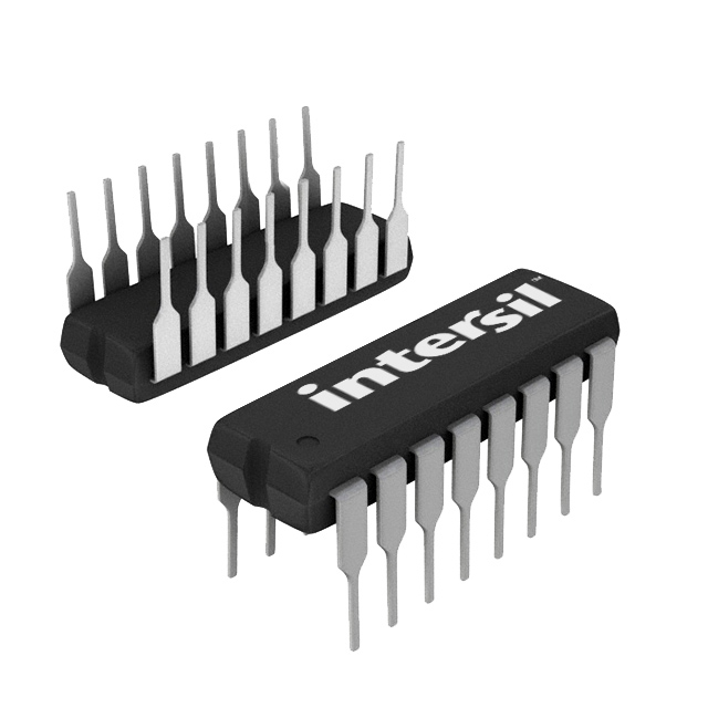
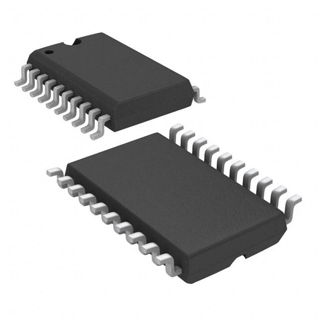
1.Package Type: Interface components are typically available in integrated circuit (IC) packages such as Dual In-Line Package (DIP), Small Outline Integrated Circuit (SOIC), Quad Flat Package (QFP), Ball Grid Array (BGA), or chip-scale packages. The package type determines the physical dimensions and pin configuration of the component, and it is important to select a package that is compatible with the system's requirements and the available board space.
2.Pin Configuration: Interface components have a certain number of pins for connecting to the system or device. The pin count can vary depending on the specific component and its functionality. Common pin configurations include 8, 16, 24, or more pins. The pinout and pin assignment should be carefully reviewed to ensure compatibility with the system's design and layout.
3.Mounting Options: Interface components can be mounted on a printed circuit board (PCB) using various mounting techniques. They may have through-hole pins for soldering into plated through-holes on the PCB, or they may have surface-mount pads for mounting using surface mount technology (SMT). The mounting option should match the PCB assembly method and manufacturing requirements.
4.Power Supply Requirements: Interface components require a power supply for their operation. The power supply requirements, such as voltage levels and current ratings, should be considered during the system design and selection of the component. Some components may have specific power supply pins, while others may derive power from the system or device they are connected to.
5.Communication Interface: Interface components often use specific communication interfaces, such as UART, SPI, I2C, Ethernet, or USB. The physical connections for these interfaces, such as data lines, clock lines, and control signals, should be considered when designing the PCB layout and making the necessary connections. The type and number of communication interface pins can vary depending on the specific component.
6.Environmental Considerations: Depending on the application environment, interface components may need additional protection or features to ensure reliable operation. This can include features like conformal coating, ESD protection, or temperature ranges suitable for the intended application. It is important to review the datasheet and specifications of the component to ensure it meets the environmental requirements of the system.
It is crucial to refer to the datasheets and specifications provided by the component manufacturers for detailed information on the physical characteristics of a specific product. Understanding these physical characteristics helps in selecting the appropriate component that can be easily integrated into the system and meet the requirements of the application.
Electrical Characteristics of Interface - Drivers, Receivers, Transceivers
The electrical characteristics of interface components such as drivers, receivers, and transceivers are crucial for their proper functioning and compatibility with the system or device they are interfacing with. Here are some important electrical characteristics to consider:
1.Supply Voltage: Interface components require a supply voltage for operation. It is essential to ensure that the supply voltage matches the requirements specified by the component datasheet. Common supply voltage levels include 3.3V and 5V, although other voltage levels may be available depending on the specific component.
2.Logic Levels: Interface components operate based on specific logic levels for input and output signals. It is important to ensure that the logic levels of the component are compatible with the system or device it is interfacing with. This includes considering voltage levels for logic high (e.g., VCC or VDD) and logic low (e.g., GND), as well as the voltage threshold for detecting high or low states.
3.Signal Voltage Levels: Interface components may have specific voltage levels for input and output signals. It is important to ensure that the voltage levels of the component are compatible with the voltage levels expected by the system or device it is interfacing with. This includes considering voltage levels for high and low signals, as well as the voltage margin or tolerance.
4.Data Rates: Interface components may have specific data rate or bandwidth specifications that determine their ability to handle high-speed data transmission. It is important to ensure that the data rate supported by the component meets the requirements of the system or application. This includes considering the maximum data rate, rise and fall times, and signal integrity at high frequencies.
5.Impedance Matching: Interface components may require impedance matching to ensure proper signal transmission and minimize signal reflections. It is important to consider the impedance characteristics of the component and the transmission line or medium it is interfacing with. This includes impedance matching techniques such as termination resistors or matching networks.
6.Communication Protocol: Interface components often support specific communication protocols such as UART, SPI, I2C, Ethernet, or USB. It is important to ensure that the component's electrical characteristics align with the requirements of the chosen communication protocol. This includes considering parameters such as voltage levels, communication speed, timing requirements, and protocol-specific features.
7.ESD Protection: Electrostatic discharge (ESD) protection is essential to prevent damage to the interface component due to electrostatic discharge events. It is important to consider the ESD protection level specified by the component manufacturer to ensure the robustness and reliability of the device.
These electrical characteristics may vary depending on the specific component model and manufacturer. It is important to refer to the datasheets and specifications provided by the component manufacturers for detailed information on the electrical characteristics of a specific component. This ensures proper integration and compatibility with the system or device while meeting the requirements of the application.

