Ⅰ. PMIC - Display Drivers
Ⅱ. Physical Characteristics of PMIC - Gate Drivers
Ⅲ. Electrical Characteristics of PMIC - Gate Drivers
PMIC, which stands for Power Management Integrated Circuit, is a crucial component in electronic devices that plays a significant role in managing and distributing power efficiently. Among the various functions performed by a PMIC, one important area is display driver control.
A display driver is responsible for controlling the operation of a display panel in electronic devices such as smartphones, tablets, laptops, and other display-equipped devices. It serves as an interface between the device's main processor or graphics processing unit (GPU) and the display panel itself.
The primary purpose of a display driver is to convert the digital signals generated by the processor or GPU into analog signals that the display panel can understand and utilize to produce the visual content. It also manages other aspects of the display panel's operation, including backlight control, power management, and various display-related features.
This is where the PMIC comes into play. In the context of display drivers, the PMIC provides the necessary power supply and voltage regulation to the display panel, ensuring stable and optimal operation. It takes the input power from the device's battery or power source and converts it into the required voltages and currents needed by the display panel.
PMICs for display drivers often incorporate advanced power management techniques to maximize power efficiency and reduce energy consumption. They may include features such as dynamic voltage scaling, which adjusts the voltage levels supplied to the display panel based on the content being shown, to optimize power consumption without compromising display quality.
Furthermore, PMICs can also handle other functions related to display drivers, such as backlight control. Backlights provide the necessary illumination for the display panel, and the PMIC can regulate the brightness levels of the backlight, allowing the user to adjust the display's overall brightness to their preferences. This control is typically achieved through pulse-width modulation (PWM) techniques.
In summary, PMICs play a critical role in display driver control by managing power supply, voltage regulation, and other essential functions related to display panels. They ensure the efficient operation of the display, optimal power management, and user-adjustable settings such as brightness control.
Physical Characteristics of PMIC - Gate Drivers
Gate drivers, which are a type of power management integrated circuit (PMIC), play a crucial role in controlling the power switches (such as MOSFETs or IGBTs) in electronic systems. They provide the necessary signals to turn these switches on and off rapidly, enabling efficient power conversion and management. Here are some physical characteristics of PMIC gate drivers:
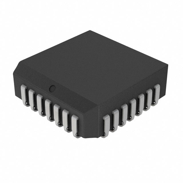
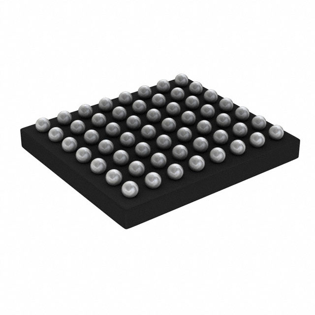
1.Package Type: Gate drivers are available in various package types, including through-hole and surface-mount packages. Common package types include DIP (Dual In-line Package), SOIC (Small Outline Integrated Circuit), and QFN (Quad Flat No-leads). The package type determines how the gate driver is mounted and connected to the circuit board.
2.Pin Configuration: Gate drivers have specific pin configurations based on their internal circuitry and functionality. The number of pins can vary, typically ranging from a few pins to more complex gate drivers with multiple pins for different control signals and power connections.
3.Voltage Rating: Gate drivers have a specified voltage rating, which indicates the maximum voltage they can handle without damage. This rating is important for selecting a gate driver that can operate within the voltage range required by the power switches it is driving.
4.Current Capacity: Gate drivers have a maximum output current capacity, which indicates the maximum current that can be sourced or sunk by the driver's output pins. This specification is crucial for ensuring that the gate driver can provide sufficient current to drive the gate capacitance of the power switches effectively.
5.Input and Output Logic Compatibility: Gate drivers can have different logic-level compatibility for their input and output signals. Common logic levels include TTL (Transistor-Transistor Logic), CMOS (Complementary Metal-Oxide-Semiconductor), and LVDS (Low-Voltage Differential Signaling). It is essential to ensure that the gate driver's logic levels are compatible with the control signals from the microcontroller or other control circuits.
6.Protection Features: Gate drivers often incorporate various protection features to enhance system reliability. These may include overcurrent protection, over-temperature protection, undervoltage lockout (UVLO), and fault detection circuits. These features help safeguard the gate driver and the power switches from potential damage or abnormal operating conditions.
7.Operating Temperature Range: Gate drivers have a specified operating temperature range within which they can function reliably. This range indicates the minimum and maximum temperatures at which the gate driver can operate without compromising performance or reliability.
It's important to refer to the gate driver's datasheet and specifications for precise information on its physical characteristics, electrical characteristics, and recommended usage guidelines.
Electrical Characteristics of PMIC - Gate Drivers
The electrical characteristics of PMIC gate drivers provide important information about their performance and compatibility with the power switches they drive. Here are some key electrical characteristics to consider:
1.Supply Voltage Range: Gate drivers have a specified supply voltage range within which they operate correctly. This range indicates the minimum and maximum voltage levels required to power the gate driver itself. It is important to ensure that the supply voltage falls within this specified range to guarantee proper functionality.
2.Output Voltage and Current: Gate drivers provide output signals to control the power switches. The output voltage refers to the voltage level at which the gate driver can drive the gate of the power switch. The output current capability specifies the maximum current that the gate driver can source or sink to charge or discharge the gate capacitance effectively.
3.Input Threshold Voltage: Gate drivers receive control signals from microcontrollers or other control circuits. The input threshold voltage indicates the minimum voltage level required for the gate driver to interpret an input signal as a logic high. It ensures that the input signals are properly recognized and processed by the gate driver.
4.Propagation Delay: Propagation delay refers to the time it takes for the gate driver's output to change state after the input signal transitions. It is an important characteristic, especially in high-frequency switching applications, as it affects the timing accuracy of the power switches.
5.Rise and Fall Times: Rise and fall times represent the time required for the output voltage of the gate driver to transition between specific voltage levels. These times impact the switching speed of the power switches and can influence the overall efficiency and performance of the system.
6.Isolation Voltage: In some applications, gate drivers require galvanic isolation between the control and power sides of the circuit. Isolation voltage specifies the maximum voltage that can be applied across the isolation barrier without causing breakdown or compromising isolation integrity.
7.Efficiency and Power Dissipation: Gate drivers can have different efficiency levels, which affects power losses and overall energy consumption. Low-power gate drivers are designed to minimize power dissipation, leading to higher efficiency and reduced thermal issues.
8.Noise Immunity: Gate drivers should exhibit good noise immunity to withstand external electrical disturbances and ensure reliable operation in noisy environments. They may incorporate noise filtering techniques or have specific noise immunity specifications to address this requirement.
These electrical characteristics vary between different gate driver models and manufacturers. It is crucial to refer to the datasheet and specifications provided by the manufacturer to understand the detailed electrical characteristics and ensure proper selection and integration of the gate driver within the system.

