Ⅰ. Introduction of inductors
Ⅱ. Structure of Inductor
Ⅲ. Working principle of inductor
Ⅳ. Basic principles of inductors
Ⅴ. Frequently Asked Questions About Inductor Energy
Ⅵ. Ideal and Real Inductors
Ⅶ. Calculation formulas related to inductors
Ⅷ.What are the four factors of inductor?
Ⅸ.What is the most common inductor?
X.What is the conclusion of inductors?
Ⅰ. Introduction of inductors
An inductor is a passive electronic component used to store and release electrical energy. It is based on the principle of inductance and is one of the important components commonly found in circuits. Inductors usually consist of a coil or coil wound around a conductor core.
An inductor will generate an electromotive force due to a change in the current passing through it, thus resisting the change in current. This property is called inductance.
Due to the change of magnetic flux formed inside the magnetic field passing through the closed current-carrying conductor, according to Faraday's law of electromagnetic induction, the closed conductor will generate an electromotive force to "resist" this change, that is, the phenomenon of electromagnetic induction. The electromagnetic induction of inductive devices is divided into self-induction and mutual induction. The electromagnetic induction phenomenon caused by the change of magnetic flux generated by its own magnetic field in the coil is called "self-induction" phenomenon; the electromagnetic induction phenomenon caused by the change of magnetic flux in the external magnetic field in the coil is called "Mutual induction" phenomenon.
An inductor is a component that converts electrical energy into magnetic energy and stores it.
Ⅱ. Structure of Inductor
Inductors can be made of a coiled core of electrically conductive material, typically copper wire, or the core can be removed or replaced with a ferromagnetic material. A core material with a higher permeability than air can more tightly confine the magnetic field around the inductive device, thus increasing the inductance. There are many kinds of inductors, most of which are made of enamel coated wire around the ferrite bobbin, while some shielded inductors have the coil completely inside the ferrite body.
The core of some inductive devices can be adjusted. In this way, the inductance can be changed. Small inductors can be etched directly onto the printed circuit board, using a method of laying out spiral traces. Small value inductors can also be used to manufacture transistors in integrated circuits using the same process.
Inductors usually consist of a coil of conductive material, usually insulated copper wire, wound around a core of plastic or ferromagnetic material; the latter are known as "iron core" inductors. The high permeability of the ferromagnetic core increases the magnetic field and confines it near the inductor, thereby increasing the inductance. Low frequency inductors are constructed similar to transformers, with electrical steel cores laminated together to prevent eddy currents.
"Soft" ferrites are widely used in cores above audio because they don't suffer as much energy loss at high frequencies as common ferrous alloys do. Inductors come in many shapes. Some inductors have an adjustable core that can vary the amount of inductance. Inductors used to block very high frequencies are sometimes made by stringing ferrite beads onto wires.
Ⅲ. Working principle of inductor
The working principle of an inductor is based on the phenomenon of inductance, the magnetic field generated when a current is conducted through a coil of wire. When current passes through an inductor, it generates a magnetic field in itself, and this magnetic field changes as the current changes.
The working principle of an inductor relies on the effects of self-inductance and mutual inductance. Self-inductance means that when current passes through an inductor, it generates a magnetic field in itself, thereby storing electrical energy. Mutual inductance means that when an inductor is close to another inductor or circuit component, they will affect each other and generate a magnetic field that induces each other.
The self-induced emf (self-induced voltage) in an inductor is proportional to the current through the coil. The faster the current change rate of the inductor, the greater the self-induced electromotive force generated, and the more obvious the effect of offsetting the current change.
1. Self-inductor
A self-inductor, also known as a self-inductance element or an inductor, is an inductive element used to store and release electrical energy.
When a current passes through the coil, a magnetic field is generated around the coil. When the current in the coil changes, the surrounding magnetic field also changes accordingly, and this changing magnetic field can cause the coil itself to generate an induced electromotive force, which is self-inductance.
A self-inductor is made up of a wire wound into a coil, and when an electric current passes through the coil, a magnetic field is generated inside the coil. According to Faraday's law of electromagnetic induction, the change of this magnetic field will cause an electromotive force to be generated inside the coil, and the direction of this electromotive force is opposite to the direction of the change of the current, trying to hinder the change of the current.
The self-inductance value of the self-inductor depends on factors such as the geometry of the coil, the number of turns of the coil, the material of the coil, and the magnetic core in the coil.

2. Transformer
When two inductance coils are close to each other, the change in the magnetic field of one inductance coil will affect the other inductance coil, and the resulting effect is mutual inductance. The size of the mutual inductance depends on the degree of coupling between the self-inductance of the inductance coil and the two inductance coils. The components made using this principle are called transformers.
A transformer consists of two or more coils wound in a common magnetic field. When the current in one coil changes, it creates a changing magnetic field that travels through the other coils, creating an electromotive force in the other coils. The direction of this electromotive force is opposite to the direction of the current change in the original coil, trying to hinder the original current change.
The phenomenon of mutual inductance makes transformers have many important applications in electronic circuits, one of the most common applications is transformers. In a transformer, two or more coils transfer electrical energy from one circuit to another through the phenomenon of mutual inductance, and realize the transformation of voltage.
Ⅳ. Basic principles of inductors
The basic principle of an inductor is based on the phenomenon of inductance. The phenomenon of inductance refers to the magnetic field generated when a current is conducted through a coil wound by a wire. When current passes through the coil of an inductor, it generates a magnetic field in itself, and this magnetic field changes as the current changes. Such a change in the magnetic field causes an electromotive force (voltage) to be generated inside the inductor, resisting the change in current and thereby storing electrical energy.
Ⅴ. Frequently Asked Questions About Inductor Energy
1. How an inductor stores energy
A pure inductor does not dissipate or dissipate energy. The only resistor is capable of converting electrical energy into heat. Pure inductors only store energy when current flows. We can say that energy is stored in the magnetic field of the inductor.
When power is supplied to an inductor or coil, it is dissipated in two ways. Part of this is used to meet I2R losses that are lost as heat. The remainder is used to create a magnetic field around the coil and is stored in the field.
Consider an inductor with an inductance L and a small resistance R connected to a DC source, powered through a switch. When the switch S is closed, the current in the inductor gradually increases and reaches a stable value. The increase in current is the opposite of the self-induced emf. Generated in an inductor due to a change in current. To overcome the resistance, some energy is provided by a source stored in the magnetic field of the inductor. Now, when the switch is turned on, the magnetic field collapses and the stored energy is released and returned to the circuit where it is dissipated as heat.
This is similar to the potential energy of lifting a weight. When an object of mass "m" is lifted to a height of "h" meters, the potential energy stored in it is "m*g*h". Work is done to lift the body up, but once it reaches a certain height, no further energy is expended to keep it in that position. This mechanical energy can be recovered by letting the body fall, and likewise electrical energy stored in the magnetic field can be recovered by the magnetic field collapsing.
2. How to deal with the energy loss of inductors
Optimized coil design: optimize the geometric structure and wire layout of the coil to reduce resistance and energy loss.
Temperature control: Through proper heat dissipation design and temperature control, ensure that the inductor works in a suitable temperature range to reduce energy loss.
Choose low-resistance materials: Choose low-resistance wire materials to reduce resistive losses. Copper is a commonly used wire material and has low electrical resistance.
Use the rated power of the inductor: Make sure the power level of the inductor matches the application requirements to avoid overload operation and reduce energy loss.
Select the appropriate operating frequency: For inductors in high-frequency circuits, selecting an appropriate operating frequency can reduce eddy current losses.Fixed Inductors
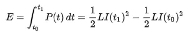
3. Calculation formula for inductor stored energy
The energy stored in an inductive device (unit: Joule) is equal to the work done by the current flowing through it to establish a magnetic field, and its value is given by:

L is the inductance, and I is the current flowing through the inductance. (Applicable only to inductive devices where the current and flux are linear and have not yet entered magnetic saturation.)
For inductive devices, the energy that can be stored in inductive devices between time t0 and t1 can be calculated by the following formula:
Ⅵ. Ideal and Real Inductors
1. Ideal inductor
The ideal inductor is a theoretical model used in the analysis and design of electronic circuits. It is a hypothetical inductor used to simplify circuit analysis and facilitate understanding and calculation of circuit behavior. In an ideal inductor, it is assumed that there are no energy losses, including resistive losses, core losses, and mutual inductance losses. An ideal inductor is one that has inductance but no resistance or capacitance and does not dissipate or radiate energy.
Features:
An ideal inductor has no resistance in its coil, and there will be no loss of energy after the current passes through it. There is no energy transfer loss with other inductors or components. The core of an ideal inductor has no energy loss during magnetization and demagnetization.
2. Actual inductor
A real inductor is an inductor that exists in the real world and corresponds to an ideal inductor. Different from ideal inductors, actual inductors will be affected by various practical factors during their working process, resulting in certain energy loss and characteristic differences.Adjustable Inductors
A real inductor not only has inductance but also resistance and capacitance. Depending on the frequency, the coil itself may behave like an LC circuit. At a certain frequency, the capacitive component of the impedance becomes dominant. The resistance of the wires dissipates energy, as does the hysteresis of the core. When a large current is applied to an actual iron core coil, it gradually deviates from ideal characteristics due to nonlinearity caused by magnetic saturation.
As frequency increases, resistance and resistive losses increase due to the skin effect of the coil winding. Core losses also lead to coil losses at high frequencies. Actual inductors can also be used as antennas. It radiates part of the energy to the surrounding space and circuits in the form of electromagnetic waves, and accepts the surrounding electromagnetic radiation as part of electromagnetic interference. Circuitry and materials surrounding the coil may interact with the coil's magnetic field, causing additional energy loss. When using real coils, these parasitic parameters are as important as the inductance. Generally, the losses in the wire are "copper losses", while the losses in the iron core are also called "iron losses".

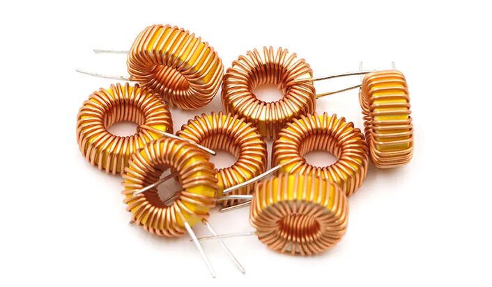
3. Coil
The coil of the inductor is the main component of the inductor, and it is also the key component for the inductor to realize the inductive effect. Coils consist of wire wound around a central or magnetic core.Wireless Charging Coils
Coils may be configured as windings of electrical conductors and typically use a ferromagnetic or ferrimagnetic material or air as a core with copper wire wound around the core. High specific air permeability can limit the use of core materials in coils, strengthening the magnetic field and thereby increasing the inductance. In the same formulation and transformer's low-frequency coils, as the core silicon steel uses, a laminate prevents eddy currents.
At frequencies above audio frequency, soft ferrites are widely used. This is because the iron loss of soft ferrite at high frequencies is smaller than that of general ferroalloys. There are coils of various shapes. The most common shape is ferritic steel bobbin which is coated with enamel copper wire windings, usually but the windings are visible, and some windings are completely surrounded by ferrite. There is also a coil whose core can be adjusted and whose inductance can be changed.
When current passes through the coil, the coil generates a magnetic field. This magnetic field propagates around the entire coil and forms the magnetic induction of the inductor. The size of the inductance is related to the number of turns of the coil and the intensity of the current. When current passes through the coil, the magnetic field generated inside the coil passes through each turn of the coil, thereby generating a self-induced electromotive force. Self-inductance is proportional to the geometry and number of turns of the coil.
Ⅶ. Calculation formulas related to inductors
1. Inductance of short cylindrical coiled coreless (air) inductance device:
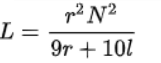
L = inductance in µH; r = outer loop radius of the wrap in inches; l = wrap length in inches; N = number of turns
2. Flat spiral air core inductor:
L = inductance in H; r = average winding radius in meters; N = number of turns; d = winding depth in meters
3. Winding inductance of toroidal core:
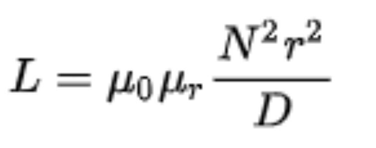
L = inductance unit H; μ0 = vacuum permeability = 4Π×10-7 H/m; μr = relative conductivity of the core material; N = number of turns; r = winding average radius in meters; Diameter in meters
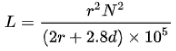
4. Multi-layer air core inductors:
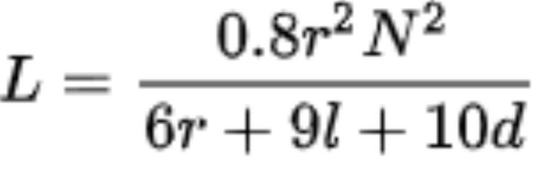
L = inductance in µH; r = average winding radius in inches; l = physical length of wire in inches; N = number of turns; d = winding depth in inches
Ⅷ.What are the four factors of inductor?
There are several physical factors which affect the inductance of a coil. They include the number of turns in the coil, the diameter of the coil, the coil length, the type of material used in the core, and the number of layers of winding in the coils.
Ⅸ.What is the most common inductor?
The commonly seen inductor, with a simple winding is this air-Core Inductor. This has nothing but air as the core material. The non-magnetic materials like plastic and ceramic are also used as core materials and they also come under this air-core Inductors.
X.What is the conclusion of inductors?
Conclusion. Inductors, like resistors and capacitors, are passive elements that store electric energy in the form of a magnetic field. They are used in the same way that resistors and capacitors are used.
Tags:inductors

